Operator’s Manual Rear Tine Tiller Model 454 IMPORTANT: Read safety rules and instructions carefully before operating equipment. Warning: This unit is equipped with an internal combustion engine and should not be used on or near any unimproved forestcovered, brush-covered or grass-covered land unless the engine’s exhaust system is equipped with a spark arrester meeting applicable local or state laws (if any). If a spark arrester is used, it should be maintained in effective working order by the operator.
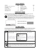
TABLE OF CONTENTS Content Important Safe Operation Practices Loose Parts Assembling Your Tiller Know Your Tiller Operating Your Tiller Making Adjustments Page 3 5 6 8 9 10 Content Servicing Your Tiller Maintaining Your Tiller Off Season Storage Trouble Shooting Guide Illustrated Parts Warranty Page 11 11 12 13 14 20 FINDING MODEL NUMBER This Operator’s Manual is an important part of your new tiller. It will help you assemble, prepare and maintain the unit for best performance.
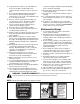
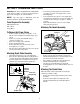
SECTION 1: IMPORTANT SAFE OPERATION PRACTICES WARNING: This symbol points out important safety instructions which, if not followed, could endanger the personal safety and/or property of yourself and others. Read and follow all instructions in this manual before attempting to operate this machine. Failure to comply with these instructions may result in personal injury. When you see this symbol - heed its warning.
. Keep bystanders, helpers, pets, and children at least 75 feet from the machine while it is in operation. Stop the machine if anyone enters the area. 5. Be careful when tilling in hard ground. The tines may catch in the ground and propel the tiller forward. If this occurs, let go of the handlebars and do not restrain the machine. 6. Exercise extreme caution when operating on or crossing gravel surfaces. Stay alert for hidden hazards or traffic. Do not carry passengers. 7.
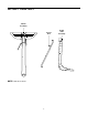
SECTION 2: LOOSE PARTS Handle Assembly Control Rod NOTE: Cable tie not shown.
SECTION 3: ASSEMBLING YOUR TILLER • IMPORTANT:This unit is shipped WITHOUT GASOLINE or OIL. After assembly, see separate engine manual for proper fuel and engine oil recommendations. • NOTE: Left and right is determined from the operator’s position, standing behind the tiller.
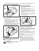
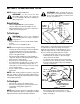
• Push the cable through the hole in the center of the handle and snap in the plastic fitting. See Figure 3. Slot Head Screw, Nut, Flat Washers Secure clutch cable to handle using cable tie. Refer to Figure 6. Cut off excess end of cable tie. Attaching The Control Rod • Internally Threaded Tube • • • Plastic Fitting Make sure the handle assembly is in the highest height position. Remove hairpin clips from control rod, (rubber washers to remain on control rod).
Tire Pressure Now move the shift lever to FORWARD (Wheels Forward) position. Carefully engage the clutch by lifting the clutch control bail against the handle. The wheels should spin. The tires on your unit may be over-inflated for shipping purposes. Reduce the tire pressure before operating the unit. Recommended operating tire pressure is approximately 20 p.s.i. (check sidewall of tire for tire manufacturer’s recommended pressure).
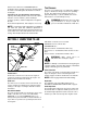
SECTION 5: OPERATING YOUR TILLER NOTE: Engine is shipped without oil. WARNING: When operating the tiller for the first time, use the depth stake setting that gives 1 inch of tilling depth (second hole from the top). See Figure 7. WARNING: Use the reverse tine drive when tilling virgin ground, sod or hard soil. Use the forward tine drive when cultivating or tilling soft ground. Before Starting • • Service engine with oil as instructed in the separate engine manual packed with your unit.
• • • WARNING: Do not move the gear selection handle with the wheels or tines engaged. Make certain the unit is stopped completely before changing the gear selection. When breaking up sod and for shallow cultivation, use the setting which gives 1" of tilling depth (second hole from the top). Place the side shields in their lowest position. For further depth, raise the depth stake and side shields and make one or two more passes over the area.
SECTION 7: SERVICING YOUR TILLER Clutch Bail—Lubricate the pivot point on the clutch bail and the cable at least once a season with light oil. The control must operate freely in both directions. Transmission—The transmission is pre-lubricated and sealed at the factory. It requires no checking unless the transmission is disassembled. To fill with grease, lay the right half of the transmission on its side. Add 30 ounces of Benalene 920 grease.
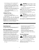
Tires Torx Screws Recommended operating tire pressure is approximately 20 p.s.i. (check sidewall of tire for tire manufacturer’s recommended pressure). Maximum tire pressure under any circumstances is 30 p.s.i. Equal tire pressure should be maintained on both tires. Belt Cover Hex Cap Nut Flat Washer When installing a tire to the rim, be certain rim is clean and free of rust. Lubricate both the tire and rim generously. Never inflate to over 30 p.s.i. to seat beads.
SECTION 10: TROUBLE SHOOTING GUIDE Trouble Possible Cause(s) Engine fails to Fuel tank empty, or stale fuel. start Throttle control lever not in correct starting position (if so equipped). Blocked fuel line. Dirty aircleaner. Choke not in ON position. Spark plug wire disconnected. Faulty spark plug. Engine flooded. Engine runs Unit running on CHOKE. erratic Spark plug wire loose. Blocked fuel line or stale fuel. Vent in gas cap plugged. Water or dirt in fuel system. Dirty air cleaner.
SECTION 11: PARTS LIST FOR MODEL 454 14
Model 454 REF. NO. 1 2 3 4 5 6 7 8 9 10 11 12 13 14 15 16 17 18 19 20 21 22 23 24 25 26 27 28 PART NO. 611-0020 611-0021 611-0128 611-0129 617-0058 617-0059 617-0060 617-0061 617-0062 686-0108 710-0376 710-0599 710-0604A 710-3008 711-1349 712-0378 712-3004A 713-0367 713-0484 716-0865 717-0853 717-1582 717-1583 717-1584 717-1585 717-1587 717-1594 721-0378 REF. NO. DESCRIPTION Wheel Shaft Ass’y: 33T Tine Shaft Ass’y: 18T Jack Shaft Ass’y Input Shaft Ass’y Rev.
Model 454 67 70 2 22 12 15 12 70 60 61 69 68 5 12 17 10 23 18 19 7 20 1 8 3 14 11 6 60 16 61 4 62 37 9 34 27 64 25 21 30 38 39 63 27 26 32 36 33 31 46 42 44 29 66 49 26 30 41 30 24 44 26 40 28 35 50 59 71 51 65 58 53 55 56 54 57 16
Model 454 REF. NO. 1 2 3 4 5 6 7 8 9 10 11 12 14 15 16 17 18 19 20 21 22 23 24 25 26 27 28 29 30 31 32 33 34 PART NO. 747-1152 649-0041 649-0034 710-3005 710-3056 711-0415 712-0379 712-0429 714-0147 720-0313 720-0210A 720-0278A 726-0317 735-0246 736-0117 736-0242 738-0958 784-0190 784-0191 786-0120 747-1219 786-0181 686-0044A 710-0176 710-3008 710-3097 712-0421 736-0169 712-3004A 726-0106 738-0849 747-0432 750-0885A REF. NO.
Model 454 18 27 46 45 12 9 19 26 6 24 17 1 8 10 25 14 2 3 28 11 13 20 15 44 21 7 40 22 4 23 5 43 42 16 41 47 39 35 38 32 33 36 37 31 34 30 29 18
Model 454 REF. NO. 1 2 3 4 PART NO. 686-0111 710-0237 710-0412 710-0502A 5 6 7 8 9 10 11 12 13 14 15 16 17 18 19 20 21 22 23 24 25 710-0152 710-0599 710-0723 712-0266 712-0267 714-0104 736-0104 736-0119 736-0176 736-0271 736-0329 736-0452 738-0876 746-1117 747-1159 754-0434 756-0405 756-0971 756-0972 756-1162 786-0064A DESCRIPTION Belt Cover Brkt. Ass’y Hex Bolt 5/16-24 x.62" Lg. Hex Bolt 1/4-28 x.75" Lg. Hex Wash.TT-Sems Screw 3/8-16 x 1.250" Lg. Hex Bolt 3/8-24 x 1.00 Hex Wash. Hd. S-Tap Scr.
MANUFACTURER’S LIMITED WARRANTY FOR: The limited warranty set forth below is given by Cub Cadet LLC with respect to new merchandise purchased and used in the United States, its possessions and territories. “Cub Cadet” warrants this product against defects in material and workmanship for a period of two (2) years commencing on the date of original purchase and will, at its option, repair or replace, free of charge, any part found to be defective in materials or workmanship.