Operator’s Manual Single Stage Snow Thrower Model 521E IMPORTANT: Read safety rules and instructions carefully Warning: This unit is equipped with an internal combustion engine and should not be used on or near any unimproved forestcovered, brush-covered or grass-covered land unless the engine’s exhaust system is equipped with a spark arrester meeting applicable local or state laws (if any). If a spark arrester is used, it should be maintained in effective working order by the operator.
TABLE OF CONTENTS Content Page Important Safe Operation Practices .................................................................. 3 Assembling Your Snow Thrower ....................................................................... 5 Know Your Snow Thrower................................................................................. 7 Operating Your Snow Thrower.......................................................................... 8 Making Adjustments............................................
SECTION 1: IMPORTANT SAFE OPERATION PRACTICES WARNING: This symbol points out important safety instructions which, if not followed, could endanger the personal safety and/or property of yourself and others. Read and follow all instructions in this manual before attempting to operate this machine. Failure to comply with these instructions may result in personal injury. When you see this symbol—heed its warning.
6. 7. 8. 9. 10. 11. 12. 13. 14. 15. 16. 17. 18. 19. 20. Maintenance & Storage Do not operate machine while under the influence of alcohol or drugs. Muffler and engine become hot and can cause a burn. Do not touch. Exercise extreme caution when operating on or crossing gravel surfaces. Stay alert for hidden hazards or traffic. Exercise caution when changing direction and while operating on slopes. Plan your snow throwing pattern to avoid discharge towards windows, walls, cars etc.
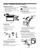
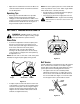
SECTION 2: ASSEMBLING YOUR SNOW THROWER Unpacking From Carton • Before Assembly Cut along corners of the carton and lay it down flat. See Figure 1. Remove packing material. Remove any loose parts included with unit (i.e., operator’s manual, etc.). Roll unit out of carton. Check carton thoroughly for any remaining loose part. • • WARNING: Disconnect the spark plug wire and ground it against the engine to prevent unintended starting.
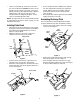
• Lift the control handle up, and hook the “Z” end of the control cable into the bottom hole in the control handle, from the outside to the inside . If necessary, pull up on the end of the cable with a pair of pliers to obtain slack in order to hook it into the control handle. Hold the “Z” fitting with the pliers, not the cable, to avoid damaging the cable. • • Secure eyebolt with 5/16” saddle washer and hex nut. The cupped side of washer goes against the handle.
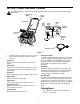
SECTION 3: KNOW YOUR SNOW THROWER Be familiar with all the controls and their proper operation. Know how to stop the machine and disengage them quickly.
SECTION 4: OPERATING YOUR SNOW THROWER Before Starting • WARNING: Read, understand, and follow Operating Snow Thrower all instructions and warnings on the machine and in this manual before operating. • ter ea nce r G sta Di The spark plug wire was disconnected for safety purposes during assembly. Attach spark plug wire to spark plug before starting. WARNING: Use extreme care when handling gasoline. Gasoline is extremely flammable and the vapors are explosive.
• Wipe all snow and moisture from the unit. Move the choke lever back and forth several times and leave it in the ON position. NOTE: Excessive upward pressure on the handle will result in premature wear on the rubber auger blades which would not be covered by warranty. • Operating Tips • • • Discharge snow downwind whenever possible. Slightly overlap each previously cleared path. Lifting up on the handle will allow the rubber on the augers to propel the snow thrower forward.
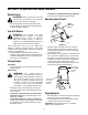
If additional adjustment is required, follow steps below. • • • Remove the belt cover by removing five hex screws that hold it in place. For location of the belt cover, see Figure 16. There are three adjustment holes provided in the idler bracket assembly. For location of these holes, see Figure 15. To adjust, move the extension spring on the end of the clutch cable to the next higher adjustment position on the idler bracket assembly. Reassemble belt cover.
WARNING: Before servicing, repairing, or • inspecting, disengage all clutch levers and stop engine. Wait until all moving parts have come to a complete stop. Disconnect spark plug wire and ground it against the engine to prevent unintended starting. • • • Pull up on the idler pulley and slip the belt off the engine pulley. Push down on the idler pulley and slip the belt off the auger pulley. Reassemble new belt. See Figure 17. Reinstall the belt cover.
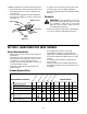
SECTION 8: TROUBLESHOOTING GUIDE Problem Engine fails to start Cause Remedy 1. Fuel tank empty, or stale fuel 1. 2. 3. 4. 5. 6. Blocked fuel line Key not in ON position Spark plug wire disconnected Faulty spark plug Gasoline and oil not mixed correctly 2. 3. 4. 5. 6. 1. 2. Unit running on choke Fuel line blocked, or stale fuel 1. 2. 3. 4. Water or dirt in fuel system Carburetor out of adjustment 3. 4. 1. Gasoline and oil not mixed correctly 1. 2. Carburetor out of adjustment 2.
SECTION 9: PARTS LIST FOR MODEL 521E 5 9 10 4 2 3 7 8 6 1 7 Ref. No. Part No. 1. 710-0487 2. 710-1270 3. 712-0324 4. 720-0284 5. 720-0295 6. 725-0157 7. 736-0451 8. 746-0883 9. 747-0956 10. 749-0711A 4 Description Carriage Screw Oval C-Sunk Machine Screw Hex Lock Nut Wing Nut Foam Grip: Handle Cable Tie Saddle Washer Cable Housing w/o Throttle Auger Bail: Gull Wing Upper Handle: Gull Wing NOTE: For painted parts, please refer to the list of color codes below.
Model 521E 19 26 11 16 26 4 2 18 17 33 15 9 7 5 28 25 6 22 35 42 45 30 13 44 6 21 38 10 3 22 7 1 30 46 37 31 34 13 35 32 23 12 20 40 6 14 27 39 8 36 14 41
Model 521E Ref. No. 1. 2. 3. 4. 5. 6. 7. 8. 9. 10. 11. 12. 13. 15. 16. 17. 18. 19. 20. 21. 22. 23. Part No. 710-0167 710-0276 710-0323 710-0451 710-0642 710-1005 710-0773 710-0896 710-3015 711-0848A 712-0429 712-3010 712-0116 712-3027 720-0284 731-0851A 731-0915B 731-0921 731-1033 732-0357A 736-0108 736-0119 Part Description Ref. No. 25. 26. 27. 28. 30. 31. 32. 33. 34. 35. 36. 37. 38. 39. 40. 41. 42. 43. 44. 45. 46.
Model 521E 17 11 28 21 10 26 7 25 2 27 7 9 23 8 6 13 15 14 19 29 4 22 24 18 7 3 16 5 5 20 16
Model 521E Ref. No. 1. 2. 3. 4. 5. 6. 7. 8. 9. 10. 11. 12. 13. 14. 15. 16. 17. 18. 19. 20. 21. 22. 23. 24. 25. 26. 27. 28. 29. Part No. Part Description 684-0054A Dash Assembly 684-0126 Chute Crank Assembly 710-1003 Special Screw: 310-16 x 0.375” 710-1090 Hex Flange Screw 5/16-18 x 1.25” 710-1268 Special screw 710-1652 Self-Tapping Screw 1/4-20 x .
Model 521E 18 15** 10 4 17 1 8 13 6 5 14 6 16 13 9 2 11 7 20 12 3 19 21 Ref. No. NOTE: For painted parts, please refer to the list of color codes below. Please add the applicable color code, wherever needed, to the part number to order a replacement part. For instance, if a part, numbered 700xxxx, is painted Cub Yellow, the part number to order would be 700-xxxx-0716. Cub Yellow: 0716 Cub Beige: 0499 Cub Blue: 0685 Powder Black: 0637 18 1. 2. 3. 4. 5. 6. 7. 8. 9. 10. 11. 12. 13. 14. 15.
Model 521E 19
MANUFACTURER’S LIMITED WARRANTY FOR: TWO-YEAR RESIDENTIAL ONE-YEAR COMMERCIAL Proper maintenance of your Cub Cadet equipment is the owner’s responsibility. Follow the instructions in your operator’s manual for correct lubricants and maintenance schedule. Your Cub Cadet dealer carries a complete line of quality lubricants and filters for your equipment’s engine, transmission, chassis and attachments.