Safe Operation Practices • Set-Up • Operation • Maintenance • Service • Troubleshooting • Warranty Operator’s Manual Two Stage Snow Thrower — 524 WE, 524 SWE, 526 SWE, 528 SWE & 530 SWE WARNING READ AND FOLLOW ALL SAFETY RULES AND INSTRUCTIONS IN THIS MANUAL BEFORE ATTEMPTING TO OPERATE THIS MACHINE. FAILURE TO COMPLY WITH THESE INSTRUCTIONS MAY RESULT IN PERSONAL INJURY. CUB CADET LLC, P.O. BOX 361131 CLEVELAND, OHIO 44136-0019 Printed In USA Form No.
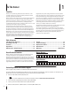
1 To The Owner Thank You Thank you for purchasing a Cub Cadet Snow Thrower. It was carefully engineered to provide excellent performance when properly operated and maintained. If applicable, the power testing information used to establish the power rating of the engine equipped on this machine can be found at www.opei.org or the engine manufacturer’s web site. Please read this entire manual prior to operating the equipment.
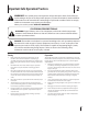
Important Safe Operation Practices 2 WARNING! This symbol points out important safety instructions which, if not followed, could endanger the personal safety and/or property of yourself and others. Read and follow all instructions in this manual before attempting to operate this machine. Failure to comply with these instructions may result in personal injury. When you see this symbol.
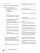
Safe Handling of Gasoline 5. To avoid personal injury or property damage use extreme care in handling gasoline. Gasoline is extremely flammable and the vapors are explosive. Serious personal injury can occur when gasoline is spilled on yourself or your clothes which can ignite. Wash your skin and change clothes immediately. Never run an engine indoors or in a poorly ventilated area. Engine exhaust contains carbon monoxide, an odorless and deadly gas. 6.
Clearing a Clogged Discharge Chute Hand contact with the rotating impeller inside the discharge chute is the most common cause of injury associated with snow throwers. Never use your hand to clean out the discharge chute. To clear the chute: 1. SHUT THE ENGINE OFF! 2. Wait 10 seconds to be sure the impeller blades have stopped rotating. 3. Always use a clean-out tool, not your hands. Maintenance & Storage 1. Never tamper with safety devices. Check their proper operation regularly.
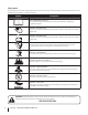
Safety Symbols This page depicts and describes safety symbols that may appear on this product. Read, understand, and follow all instructions on the machine before attempting to assemble and operate. Symbol Description READ THE OPERATOR’S MANUAL(S) Read, understand, and follow all instructions in the manual(s) before attempting to assemble and operate WARNING— ROTATING BLADES Keep hands out of inlet and discharge openings while machine is running.
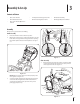
3 Assembly & Set-Up Contents of Carton • One Snow Thrower • Two Replacement Auger Shear Pins • One Chute Assembly • One Chute Control Rod • One Product Registration Card • One Engine Operator’s Manual • One Snow Thrower Operator’s Manual Assembly Remove all loose parts before assembling. Handle Assembly 1. Place the shift lever in the Forward-6 position 2.
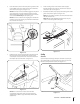
2. Insert chute control rod into chute control head. Push rod as far into chute control head as possible, keeping the holes in the rod pointing upward. See Figure 3-4. 4. Squeeze the trigger on the joystick and rotate the chute by hand to face forward. The holes in the chute control input will be facing up. See Figure 3-6. Chute Control Input Figure 3-4 3. Place chute onto chute base and ensure chute control rod is positioned under the handle panel.
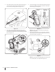
6. Insert the chute control rod into the pinion gear below the joystick. Make sure to line up the hole in the rod with the arrow on the pinion gear. See Figure 3-8. 8. Finish securing chute control head to chute support bracket with wing nut, clevis pin, and bow-tie cotter pin removed in step 1. See Figure 3-3. NOTE: The chute control rod will fit snuggly into the pinion gear.
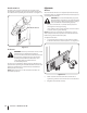
Chute Clean-Out Tool Adjustments The chute clean-out tool is fastened to the top of the auger housing with a mounting clip and a cable tie at the factory. Cut the cable tie before operating the snow thrower. See Figure 3-12. Skid Shoes The snow thrower skid shoes are adjusted upward at the factory for shipping purposes. Adjust them downward, if desired, prior to operating the snow thrower.
Auger Control Chute Assembly WARNING! Prior to operating your snow thrower, carefully read and follow all instructions below. Perform all adjustments to verify your snow thrower is operating safely and properly. Check the adjustment of the auger control as follows: 1. When the auger control is released and in the disengaged “up” position, the cable should have very little slack. It should NOT be tight. 2. In a well-ventilated area, start the snow thrower engine.
4 Controls and Features Drive Control Shift Lever Chute Directional Control Auger Control Headlight † Heated Grips † Steering Trigger Control † Chute Assembly Clean Out Tool Augers Skid Shoe † If Equipped Figure 4-1 Snow thrower controls and features are described below and illustrated in Figure 4-1. Shift Lever The shift lever is located in the right side of the handle panel and is used to determine ground speed and direction of travel. Forward There are six forward (F) speeds.
Auger Control Heated Grips (If so Equipped) CAUTION: It is recommended that you wear gloves when using the heated grip. If the heated grip become too hot, turn it off. The auger control is located on the left handle. Squeeze the control grip against the handle to engage the augers and start snow throwing action. Release to stop. To activate the heated grips, move the switch found on the rear of the dash panel into the ON position.
2-Way Chute Directional Control (If so Equipped) Chute Clean-Out Tool WARNING! Never use your hands to clear a clogged chute assembly. Shut off engine and remain behind handles until all moving parts have stopped before unclogging. The chute clean-out tool is conveniently fastened to the rear of the auger housing with a mounting clip.
5 Operation Starting and Stopping the Engine Replacing Shear Pins Refer to the Engine Operator’s Manual packed with your snow thrower for instructions on starting and stopping the engine. The augers are secured to the spiral shaft with shear pins and cotter pins. If the auger should strike a foreign object or ice jam, the snow thrower is designed so that the pins may shear. If the augers will not turn, check to see if the pins have sheared. See Figure 5-2. To Engage Drive 1.
6 Maintenance & Adjustments Maintenance Lubrication Engine Wheels Refer to the Engine Operator’s Manual. Tire Pressure At least once a season, remove both wheels. Clean and coat the axles with a multipurpose automotive grease before reinstalling wheels. Refer to Assembly and Set-up section for information regarding tire pressure. Auger Shaft Shave Plate and Skid Shoes The shave plate and skid shoes on the bottom of the snow thrower are subject to wear.
Gear Shaft Adjustments The gear (hex) shaft should be lubricated at least once a season or after every twenty-five (25) hours of operation. Shift Cable 1. Allow the engine to run until it is out of fuel. 2. Carefully pivot the snow thrower up and forward so that it rests on the auger housing. If the full range of speeds (forward and reverse) cannot be achieved, adjust the shift cable as follows: 3.
Drive Control Chute Control Rod When the drive control is released and in the disengaged “up” position, the cable should have very little slack. It should NOT be tight. To adjust the chute control rod, proceed as follows: 1. NOTE: If excessive slack is present in the drive cable or if the snow thrower’s drive is disengaging intermittently during operation, the cable may be in need of adjustment. Remove the hairpin clip from the hole closest to the chute assembly on the chute rotation assembly. 2.
7 Service Belt Replacement 4. Auger Belt Carefully pivot the snow thrower up and forward so that it rests on the auger housing. 5. Remove the frame cover from the underside of the snow thrower by removing the self-tapping screws which secure it. See Figure 7-3. To remove and replace your snow thrower’s auger belt, proceed as follows: 1. Allow the engine to run until it is out of fuel. Do not attempt to pour fuel from the engine. 2.
7. Remove the belt from around the auger pulley, and slip the belt between the support bracket and the auger pulley. See Figure 7-5. Drive Belt To remove and replace your snow thrower’s drive belt, proceed as follows: 1. To prevent spillage, remove all fuel from tank by running engine until it stops. Do not attempt to pour fuel from the engine. 2. Remove the plastic belt cover on the front of the engine by removing the two self-tapping screws. Refer to Figure 7-1. 3. Remove the belt as follows: a.
6. Back out the stop bolt to increase the clearance between the friction wheel disc and friction wheel. See Figure 7-7. Friction Wheel Removal (524 WE) If the snow thrower fails to drive with the drive control engaged, and performing the drive control cable adjustment fails to correct the problem, the friction wheel may need to be replaced. Follow the instructions below. Examine the friction wheel for signs of wear or cracking and replace if necessary: Stop Bolt 1.
5. Carefully remove the hex nut which secures the hex shaft to the snow thrower frame and lightly tap the shaft’s end to dislodge the ball bearing from the right side of the frame. See Figure 7-9. 7. Follow the previous steps in reverse order to reassemble components. 8. NOTE: Be careful not to damage the threads on the shaft. Perform the Drive Control test on page 18 in the Maintenance and Adjustments section.
8 Troubleshooting Problem Engine fails to start Cause Remedy 1. Choke not in CHOKE position. 1. Move choke to CHOKE position. 2. Spark plug wire disconnected. 2. Connect wire to spark plug. 3. Fuel tank empty or stale fuel. 3. Fill tank with clean, fresh gasoline. 4. Engine not primed. 4. Prime engine as instructed in the Engine Operator’s Manual. 5. Faulty spark plug. 5. Clean, adjust gap, or replace. 6. Key not in ignition on engine. 6. Insert key fully into the switch. 1.
9 Replacement Parts Component Part Number and Description 954-04050 954-04260 954-04195 954-04201A Auger Drive Belt (524 WE & 524 SWE) Wheel Drive Belt (524 WE & 524 SWE) Auger Drive Belt (526 SWE, 528 SWE & 530 SWE) Wheel Drive Belt (526 SWE, 528 SWE & 530 SWE) 684-04159 684-04153 935-04054 Friction Wheel Assembly (524 SWE, 526 SWE, 528 SWE, 530 SWE) Friction Wheel Assembly (524 WE) Friction Wheel Rubber (all models) 925-1629 Lamp, 12V 738-04124A 714-04040 Shear Pin, 1.
10 Attachments & Accessories The following attachments and accessories are available for your Cub Cadet snow thrower. See your Cub Cadet dealer or the retailer from which you purchased your snow thrower for information regarding price and availability.
Notes 26 11
Section 11 — Notes 27
CUB CADET LLC MANUFACTURER’S LIMITED WARRANTY FOR SNOW THROWERS The limited warranty set forth below is given by Cub Cadet LLC with respect to new merchandise purchased and used in the United States, its possessions and territories, and by MTD Products Limited with respect to new merchandise purchased and used in Canada and/or its territories and possessions. This warranty is in addition to any applicable emissions warranty provided with your product.