Hydrostatic Zero-Turn Commercial Riding Mower Professional Turf Equipment MODEL 19HP Tank, 53BB5DAV150 20HP Tank, 53AB5E6V150 23HP Tank, 53BB5DBW150 24HP Tank, 53AB5ETW150 25HP Tank, 53AB5D8X150 27HP Tank, 53AB5BDX150 28HP Tank, 53AB5FEZ150 OPERATOR’S AND SERVICE MANUAL
TABLE OF CONTENTS Foreword. . . . . . . . . . . . . . . . . . . . . . . . . . . . . . . . . . . . . . . . . . . . . . . . . . . . . . . . . . . . . . . 3 General Safety Operations . . . . . . . . . . . . . . . . . . . . . . . . . . . . . . . . . . . . . . . . . . . . . . . . . 4 A.Danger . . . . . . . . . . . . . . . . . . . . . . . . . . . . . . . . . . . . . . . . . . . . . . . . . . . . . . . . . . 4 B. Warning . . . . . . . . . . . . . . . . . . . . . . . . . . . . . . . . . . . . . . . . . . . . . . .
FORWARD The Tank Hydrostatic Zero-Turn Commercial Riding Mower provides superb maneuverability, mid-mount cutting capability for professional landscapers, commercial lawn service companies, professional turf managers and golf course superintendents. The machine incorporates many safety features that should be studied by all operators and maintenance personnel before use. The list of safety precautions should receive particular attention.
GENERAL SAFETY OPERATIONS 6. 7. A. DANGER 1. 2. 3. 8. Do not operate machine in confined areas where exhaust gases can accumulate. Do not operate machine without mower chute deflector in place and operational. Do not carry passengers. 9. 10. B. WARNING 1. Do not operate machines under the influence of alcohol or drugs. 2. Do not operate machines without all guards and safety devices in place and functional. 3. Do not start machines if there are fuel or oil leaks or spillage — clean it up. 4.
11. When looking for oil leaks, never run your hand over hydraulic hoses, lines or fittings. Never tighten or adjust hydraulic hoses, lines or fittings while the system is under pressure. If high-pressure oil penetrates the skin, the oil must be removed within a few hours by a doctor familiar with this form of injury or serious complications may result. 3. 4. 5. 6. B. Related to Fuel 1. Fuel is highly flammable and its vapors can explode if ignited. Please respect it. 2.
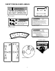
SAFETY DECALS AND LABELS WARNING SHIELD MISSING DO NOT OPERATE Part Number: 00030635 Part Number: 01003858 DANGER ROTATING BLADE Do not put hands or feet under or into mower when engine is running. Part Number: 01003449 Part Number: 00030633 Part Number: 01003450 Part Number: 01003859 Part Number: 01002166 T O R E D U C E T H E R I S K O F I N J U R Y, D O N O T O P E R AT E M O W E R U N L E S S DISCHARGE CHUTE COVER OR GRASS C AT C H E R I S I N I T S P RO PE R P L AC E .
SPECIFICATIONS Engine: Type: Air Cleaner: Lube System: Starter: Traction Drive: Hydraulic Tank: Cutter Deck;Drive: Clutch: Deck Lift: Cutting Height: No.
OPERATING INSTRUCTIONS Figure. 1 Electric Blade Clutch Switch Figure. 2 Tach and Hour Meter Engine throttle Choke Lever Ignition Switch A.General ing and raise the cutting deck to the transport position. Always allow other vehicles to have the right of way. l.
B.Controls c. Avoid turning when going downhill, traction is at a minimum going downhill. d. Do not operate with discharge side of the mower toward streets, buildings, playgrounds, parking lots, other machines, animals, and other people. e. Avoid operation or use extreme care if the traction surface is wet, unstable, or slippery. f. Use extra care when grass clippings, leaves, pine needles, or debris are present as traction can be reduced. g.
Steering Levers Deck Lift Handle Note: The 19hp and 23hp use the 5 gallon fuel tank. Brake Figure. 4 Fuel Shutoff Valve Figure. 3 4. Electric Blade Clutch Switch: (See Figure 1.) Located on the right side of the mower beside the ignition switch. This is an “on/off” push pull switch that controls the electric blade clutch which supplies power to the cutting blades through the PTO.
C.Initial Adjustments the procedures below to set the appropriate angle to the mowing deck. a. Park the mower on a flat paved surface, engage the parking brake, shut off the engine, remove the key from the ignition switch, remove connection of the spark plugs and using the transport lever, lower the mowing deck into the cutting position. b.
clockwise a few turns. Adjust both front and rear Deck links as necessary. Retighten nuts. f. Raise the mowing deck to the transport position using the transport lever. g. Use the transport lever to lower the mowing deck to the cutting position and repeat step “b.” above to make sure that the desired cutting height has been attained. If the dimensions are not correct, repeat steps “c.” through “f.” above. d. Inspect the machine to make sure: 1.
run. Turn off the PTO by pushing the control switch down. h. To drive in the FORWARD direction: 1. Set the engine speed to 2000 to 2500 rpm (refer to tachometer on right control panel). This must be increased to full speed (3525-3675 rpm) after becoming familiar with the machine. 2. Release the park brake. 3. Move both lap bars out of the neutral/ start position to the neutral position (toward center of machine).
e. Push the throttle control to a position a third of the way between slow and fast. f. Insert the key in the ignition and start switch and turn the switch to “On”. g. Gasoline Engine: If the engine is cold, push the choke to the on position. h. Turn the ignition key in a clockwise direction to the “Start” position until the engine starts. i. j. Note: Do not hold the key in the “Start” position for more than 10 seconds or you may damage the starter.
Linch Pins Linch Pins Figure. 6 Height of Cut Clevis Pin a. Set the parking brake. b. Clean any debris from the blades. Keep blades sharp and free of build up at all times. c. Sharpen blades evenly at the original 30° angle to maintain balanced cutting blades. Do not sharpen the underside of the blades. Use a electric blade sharpener, a conventional electric grinder or a hand file to sharpen the blades. d. Replace any blade with severe nicks or dents that cannot be removed by filing. e.
Cover Plate Spindle Figure. 8 1. Hydraulic Tank Adding Hydraulic Oil (use SAE20W 50) Place the Mower on a level surface and engage the parking brake. b. Stop the engine and remove the key from the ignition switch. c. Clean the area around the Hydraulic Oil fill neck. d. Remove the hydraulic fill cap and check the level. The correct level is up to the lowest hole of the oil tank fill neck. e. Pour hydraulic oil into the reservoir up to the lowest hole in the oil tank fill neck, if necessary. a. Figure.
caps and drain oil from both left and right pumps. Replace and retighten nuts. c. Hydraulic pumps Figure. 9 Unfasten hose and drain from this side of both pumps. Store the battery with a full charge. A discharged battery will freeze (refer to the table below). Specific Gravity Freezing Temp (°F) 1.265 -71 1.250 -62 1.200 -16 1.150 5 1.100 16 d. Recharge battery when ever the specific gravity value is less than 1.225 3. Battery Removal j. Coat new filter seal with oil before installation.
other electrical components. This is a standard plug-in type automotive fuse rated at 7.5 amp. 7. Safety Switches: There are five safety switches in the electrical circuit which control the engine. They are (1) the blade clutch switch, (2) the parking brake switch, (3) the left and (4) the right steering lever switches and (5) the seat switch.
does not stop, the seat switch must be replaced. With both steering levers folded out in the neutral position, the parking brake engaged and the blade clutch switch in the “off” position, sit in the operator’s seat and start the engine. Turn the blade clutch switch to the “on” position and the blades should start to rotate. Raise up slightly off the operator’s seat and the blades should stop. If the blades do not stop when you dismount from the operator’s seat, the seat switch must be replaced. e.
d. Loosen jam nuts on both ends of rod connectors. See Control Assembly in the Illustrated Parts Book (ONLY if mower creeps.) e. Start unit and push throttle all the way on. f. If unit creeps forward rotate rear rod connectors counter-clockwise. And if unit creeps in reverse, rotate clockwise. pin from the clevis pin and pulling the clevis pin from the brake clevis. Loosen the hex nut and turn the brake clevis in a clockwise direction one full turn looking down the brake rod.
3. Hydrostatic Pumps and Motors: The pumps are the hardest-working components in the hydraulic system. They are in operation all the time the engine is running. Because of extremely close tolerances, wear is an important factor in their life. Contaminants in the hydraulic oil and cavitation does the greatest harm to the pumps. Cavitation is a blockage in the supply lines that produces a partial vacuum causing violent bubbling in the hydraulic oil in the pump. prevents the rod end bearing from turning.
into an approved fuel container. Open the fuel tank shutoff valve and drain the fuel tank and line into the approved container. Replace the fuel line on the carburetor. Start the engine and allow it to run out of fuel. This will prevent gum and varnish deposits from forming. Replace the fuel filter. g. Gasoline Engine Only: Remove the spark plugs and pour approximately one ounce of oil into each cylinder. Crank the engine one or two turns to spread the oil evenly on the cylinder walls.
. OIL CHART Apply a few drops of SAE 20W-50 engine oil or use a spray lubricant. Apply the oil to both sides of pivot points. Wipe off any excess. Start engine and operate mower briefly to insure that oil spreads evenly.
Performance Adjustments B. Enginge RPM Check and Adjustment Description A. High Speed Tracking Adjustment If mower tracks to one side with both lap bars in fully forward position: 1. 2. 3. 4. 5. Check air pressure in all four tires: a. Pressure should be within specified ranges and balanced side-to-side. b. Rear tires 8-10 psi. recommended (20 psi MAX.) c. Front tires 20-25 psi. recommended (28 psi MAX. Check hydraulic fluid level (Ref.
f. Repeat as required to obtain proper throttle adjustment. g. Verify proper throttle adjustment by checking RPM readings as outlined above. a. Adjustment lever is located under the front edge of the seat. b. 3. C. Deck Corner Ball Wheel Roller Settings 1. Matching the set heights of the ball rollers on the four corners of the mower deck to the desired cut height will prevent edge scalping and minimize any side-to-side variance in cut height. 2.
F. Deck leveling Procedure 1. 2. 3. 4. 5. 6. 7. aligned along the mower centerline. The bladeto-ground height at the rear of the blade tip should be 1/8" to 1/4” higher than the front tip. This is referred to as blade pitch. The sam height difference should be true for the left blade, measured front and back. 8. To adjust the blade pitch the deck pitch must be adjusted. Loosen the inner jam nuts at the rear of the horizontal threaded rods.
WIRING DIAGRAM 27
MAINTENANCE RECORD DATE WORK PERFORMED DATE 28 WORK PERFORMED
MAINTENANCE RECORD DATE WORK PERFORMED DATE 29 WORK PERFORMED
MAINTENANCE RECORD DATE WORK PERFORMED DATE 30 WORK PERFORMED
MAINTENANCE RECORD DATE WORK PERFORMED DATE WORK PERFORMED
MANUFACTURER’S LIMITED WARRANTY - TURF EQUIPMENT This warranty is specific to the product manual to which it is attached. For a complete list of products and warranties contact your authorized Cub Cadet Commercial dealer. Proper maintenance of the purchased Cub Cadet Commercial equipment is the owner’s responsibility. Follow the instructions in your owner’s manual for correct lubricants and maintenance schedule.