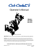
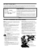
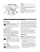
Operator’s Manual Models 724 STE 926 STE Model 926 STE shown IMPORTANT: Read safety rules and instructions carefully before operating equipment. Warning: This unit is equipped with an internal combustion engine and should not be used on or near any unimproved forestcovered, brush-covered or grass-covered land unless the engine’s exhaust system is equipped with a spark arrester meeting applicable local or state laws (if any).
TABLE OF CONTENTS Content Page Important Safe Operation Practices................................................................... 3 Loose Parts ....................................................................................................... 5 Assembling Your Snow Thrower ....................................................................... 5 Know Your Snow Thrower ................................................................................. 7 Operating Your Snow Thrower ...................
SECTION 1: IMPORTANT SAFE OPERATION PRACTICES This symbol points out important safety instructions which, if not followed, could endanger the personal safety and/or property of yourself and others. Read and follow all instructions in this manual before attempting to operate this machine. Failure to comply with these instructions may result in personal injury. When you see this symbol—heed its warning.
5. 6. 7. 8. 9. 10. 11. 12. 13. 14. 15. 16. 17. 18. 19. 20. Maintenance And Storage Never run an engine indoors or in a poorly ventilated area. Engine exhaust contains carbon monoxide, an odorless and deadly gas. Do not operate machine while under the influence of alcohol or drugs. Muffler and engine become hot and can cause a burn. Do not touch. Exercise extreme caution when operating on or crossing gravel surfaces. Stay alert for hidden hazards or traffic.
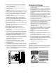
SECTION 2: LOOSE PARTS The snow thrower is shipped with the following loose parts in the carton. Please remove all loose parts from the carton before discarding it. See below to identify the parts, noting that these parts may be referred to again in the following sections of the manual. Part numbers are shown in parentheses. Auger Shear Bolts Shear Bolts (710-0890A) Hex Lock Nuts (712-0429) The augers are secured to the auger shaft with two shear bolts and hex lock nuts.
• • Shift Rod Connector Hex Nut Loosen the jam nut and thread the cable in (for less slack) or out (for more slack) as necessary. See Figure 5 . Recheck the adjustment before retightening the jam nut against the cable. Traction Control and Shift Lever Adjustment NOTE: It is easier to maneuver a non-running snow thrower with both track steering controls held in simultaneously.
• Loosen the jam nut on the traction control cable (located opposite the auger control cable) and UNTHREAD the cable one full turn. • Recheck the adjustment. • Retighten the jam nut to secure the cable when the correct adjustment is reached. If the machine can be moved freely both forward and rearward with the traction control fully depressed, proceed as follows: • • • • • Loosen, but do NOT remove, the three hex nuts which fasten the skid shoe to the auger housing.
Traction Control / Auger Control Lock NOTE: The heated grips are a compliment, NOT a substitute for proper cold weather outerwear for hands. It is recommended that the user wear gloves/mittens when operating this snow thrower. The traction control is located on the right handle. See Figure 7. Squeeze the traction control to engage the wheel drive. Release to stop.
Headlight The headlight is on whenever the engine is running. Primer Throttle Control The throttle control is located on the engine. It regulates the speed of the engine and will shut off the engine when pushed down completely. See Figure 9. Switch Box Choke Safety Ignition Key Ignition Key Recoil Starter Handle Throttle Control The safety ignition key must be fully inserted in the switch before the unit will start. Remove the ignition key when the snow thrower is not in use. See Figure 9.
• • To Engage Track Drive Connect the power cord (electric start) to the switch box on the engine. Plug the other end of power cord into a three-hole, grounded 120 volt AC receptacle. Push the primer button three times. If the engine is warm, push the primer button once only. See Figure 9. • NOTE: Use slower speeds in higher snow and until NOTE: Always cover the vent hole in the primer you are familiar with the operation of the snow thrower. button when pushing.
SECTION 6: MAKING ADJUSTMENTS WARNING: NEVER attempt to make adjustments WARNING: Drain the gasoline out of your while the engine is running, except where specified in the operator’s manual. snow thrower’s engine, or place a piece of plastic film under the gas cap to avoid spillage before making this adjustment. Chute Directional Adjustment • The distance snow is thrown can be adjusted by adjusting the angle of the chute assembly. Refer to the Chute Tilt Control in the Know Your Snow Thrower Section.
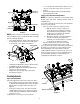
Shift Rod Adjustment Drive Shaft To adjust the shift rod, proceed as follows. • Drive Cable Sprocket Shaft • • • Pivot Rod Friction Wheel Rubber • Drive Plate Remove the hairpin clip and slide the clutch rod connector up, to separate the upper shift rod from the lower shift rod. See Figure 10. Place the shift lever into the sixth (6) position. Rotate the shift arm clockwise (from the operator’s position) as far as it will go.
Traction Control / Auger Control Lock Grease Fittings The cams on the ends of the control rods which interlock the traction drive and auger drive levers must be lubricated at least once a season or every 25 hours of operation. The cams can be accessed beneath the handle panel. Use a multi-purpose automotive grease. Vent Plug Shear Bolts Gear Case The gear case is lubricated with grease at the factory. Every 25 hours or once a season, remove the vent plug located on the top of the gear case.
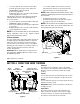
Belt Removal And Replacement Wheel Drive Pulley WARNING: Disconnect the spark plug wire and ground it against the engine before performing any repairs or maintenance. Auger Drive Pulley Auger Belts • • • Remove the plastic belt cover at the front of the engine by removing the two self-tapping screws. See Figure 15. Drain the gasoline from the snow thrower, or place a piece of plastic film under the gas cap. Tip the snow thrower up and forward so that it rests on its auger housing.
• Friction Wheel • Drive Plate Drive Belt Reassemble the new friction wheel rubber to the friction wheel plates and hub, tightening the six screws in rotation and with equal force. Position the friction wheel assembly up onto the pin of the shift rod assembly, and slide the shaft through the assembly. Reassemble in reverse order. NOTE: If you placed plastic film under the gas cap, be Stop Bolt certain to remove it.
• • NOTE: When storing any type of power equipment in an poorly ventilated or metal storage shed, care should be taken to rustproof the equipment, especially springs, cables and all moving parts. Follow “Storage” instructions in the Engine Manual. Store in a clean, dry area. Block the snow thrower up so it is not resting on the rubber auger blades. SECTION 9: TROUBLE SHOOTING Problem Cause Remedy Engine fails to start 1. 2. 3. 4. 5. 6. 7. 8. Fuel tank empty, or stale fuel. Blocked fuel line.
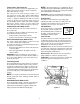
SECTION 10: Models 724 STE / 926 STE 4 17 11 9 16 13 8 15 1 10 14 5 18 6 3 7 12 2 Ref. No. Part No. 3 Part Description 1. 618-0123 RH Housing 2. 618-0418 LH Housing w/Fitting 3. 710-0642 Self Tapping Screw, 1/4-20 x .75 4. 711-0908A 711-0909A Spiral Axle, 24” (724 STE) Spiral Axle, 26” (926 STE) 5. 714-0161 Hi-Pro Key, 3/16 x 5/8 6. 715-0143 Spring Spiral Pin, .25 x 1.25 7. 717-0528 Worm Gear, 20-tooth 8. 717-0526 Worm Shaft 9. 718-0186 Thrust Collar 10.
Models 724 STE / 926 STE 68 57 58 27 70 57 58 55 65 53 72 73 72 69 82 27 27 71 68 92 80 74 63 59 67 69 27 56 64 58 66 62 77 60 66 78 58 54 81 76 31 45 79 11 75 61 45 15 9 29 51 5 40 5 46 37 47 5 2 8 14 13 17 24 5 20 22 10 14 21 3 50 9 11 40 85 84 16 41 4 10 19 43 9 86 87 42 27 35 39 91 9 6 23 10 14 88 11 44 32 28 90 89 For reference only 7 44 For reference only 15 83 14 36 48 10 49 11 52 7 35 38 1 12 26 25 31 18 30 18
Models 724 STE / 926 STE Ref. No. 1. 2. 3. 4. 5. 6. 7. 8. 9. 10. 11. 12. 13. 14. 15. 16. 17. 18. 19. 20. 21. 22. 23. 24. 25. 26. 27. 28. 29. 30. 31. 32. 35. 36. 37. 38. 39. 40. 41. 42. 43. 44. 45. 46. 47. 48. Part No. 684-0008A Ref. No. Part Description 49. 50. 51. 52. Shift Arm Assembly 710-0262 Carriage Bolt 5/16-18 x 1.5” 710-0449 Carriage Bolt 5/16-18 x 2.25” 710-0788 TT Screw 1/4-20 x 1” 710-0837 C-Sunk Screw #10-16x .625”† 710-0890A Shear Bolt 5/16-18 x 1.
Models 724 STE / 926 STE 2 3 1 4 5 11 10 9 15 18 14 12 7 6 8 13 16 22 23 27 34 21 10 28 25 23 9 13 38 26 30 35 19 18 22 32 31 33 16 41 37 36 17 39 40 24 40 39 29 42 20 20
Models 724 STE / 926 STE Ref. No. Part No. Ref. No. Part Description Part No. Part Description Lock Jam Nut 3/8-24 23. 736-0463 756-0178 Flat Idler 24. 784-0399 Bearing Housing w/Fitting 3. 784-5632A Auger Idler Arm 25. 710-0703 Carriage Screw 1/4-20 x .75 4. 710-0459A Hex Cap Screw 3/8-24 x 1.50 26. 710-0604 Hex Screw 5/16-18 5. 738-0281 Shoulder Screw 27. 736-0169 Lock Washer 3/8 6. 736-0167 Flat Washer 28. 712-0798 Hex Nut 3/8-16 7. 732-0611 Extension Spring 29.
Models 926 STE 28 29 30 1 27 1 2 26 3 4 9 8 4 7 11 10 16 19 12 15 6 5 16 19 16 21 16 22 13 23 14 18 17 25 20 24 IMPORTANT: For a proper working machine, use Factory Approved Parts. V-BELTS are specially designed to engage and disengage safely.
Models 926 STE Ref. No. Part No. Part Description 1. 710-1652 Hex Washer Screw 1/4-20 x .625 2. 731-1324 Belt Cover 3. 732-0710 Extension Spring 4. 710-0627 Hex Screw 5/16-24 x .75 5. 710-3005 Hex Cap Screw 3/8-16 x 1.25 6. 05896A Drive Clutch Idler Bracket 7. 748-0234 Shoulder Spacer 8. 756-0987 Pulley Half 9. 754-0346 V-Belt 10. 756-0986 Pulley Half 11. 736-0270 Bell Washer 12. 710-0230 Hex Cap Screw 1/4-28 x .50 13. 756-0313 Flat Idler 14.
Model 724 STE 1 2 29 30 28 31 32 3 11 20 8 22 27 3 23 9 15 26 2 24 21 24 14 16 5 12 1 6 13 17 18 19 4 25 IMPORTANT: For a proper working machine, use Factory Approved Parts. V-BELTS are specially designed to engage and disengage safely.
Model 724 STE Ref. No. Part No. Part Description 1. 05896A Drive Clutch Idler Bracket 2. 710-0230 Hex Cap Screw 1/4-20 3. 710-0627 Hex Cap Screw 5/16-24 4. 710-0654A Hex Screw 3/8-16 x 1.0 5. 710-0696 Hex Cap Screw 3/8-24 6. 710-1245 Lock Hex Cap Screw 6/16-24 7. 710-1652 Hex Washer Screw 1/4-20 x .625 8. 710-3005 Hex Cap Screw 3/8-16 x 1.25 9. 712-0181 Lock Jam Nut 3/8-16 10. 731-1324 Belt Cover 11. 732-0339 Extension Spring 12. 736-0159 Washer 5/16 13.
Models 724 STE / 926 STE 22 23 34 24 25 30 19 21 29 26 32 2 31 32 27 20 30 19 18 17 26 16 27 2 19 25 24 23 22 20 10 2 18 19 14 15 3 21 36 11 28 13 4 1 9 7 5 6 39 38 32 2 37 40 32 26 30 12
Models 724 STE / 926 STE Ref. No. Part No. Ref. No. Part Description Part No. Part Description 1. 784-5648 Frame Cover 21. 710-0875 Tap Screw, 1/4-20 x .75 2. 710-1652 Tap Screw, 1/4-20 x .625 22. 736-0270 Bell Washer, .265 x .75 x .062 3. 748-0190 Spacer, .508 ID x .75 OD x .68 23. 736-0176 Flat Washer, 1/4 ID x .93 OD x .12 4. 732-0264 Ext. Spring 24. 741-1111 Hex Flange Bearing 5. 712-0711 Jam Nut, 3/8-24 25. 710-0643 Hex Cap Screw, 5/16-18 x 1 6.
Models 724 STE / 926 STE 44 43 45 54 51 1 50 47 46 2 42 41 51 53 54 55 52 48 3 5 46 49 9 6 4 38 30 37 12 8 19 7 13 11 56 10 16 36 20 32 26 15 35 33 23 37 29 56 27 22 17 28 34 31 20 25 14 18 33 30 32 19 21 24 22 26 39 40 16 21 18 15 14 17 28 13
Models 724 STE / 926 STE Ref. No. Part No. Ref. No. Part Description Part No. Part Description 1. 720-0223 Grip 29. 618-0169 Track/Steering Shaft Assy 2. 710-0604 Tap Screw, 5/16-18 x .625 30. 684-0154 Track Hub Assy w/Fitting 3. 784-5642 Track Lockout Plate 31. 713-0437 Chain 4. 710-0157 Hex Cap Screw, 5/16-24 x .75 32. 741-0339 Flange Bearing 5. 736-0242 Bell Washer, .34 ID x .872 OD 33. 736-0287 Flat Washer, .793 x 1.24 x .06 6.
MANUFACTURER’S LIMITED WARRANTY FOR: TWO-YEAR RESIDENTIAL ONE-YEAR COMMERCIAL Proper maintenance of your Cub Cadet equipment is the owner’s responsibility. Follow the instructions in your operator’s manual for correct lubricants and maintenance schedule. Your Cub Cadet dealer carries a complete line of quality lubricants and filters for your equipment’s engine, transmission, chassis and attachments.