Operator’s Manual SNOW THROWER MODEL 730 STE IMPORTANT: READ SAFETY RULES AND INSTRUCTIONS CAREFULLY WARNING: This unit is equipped with an internal combustion engine and should not be used on or near any unimproved forestcovered, brush-covered or grass-covered land unless the engine’s exhaust system is equipped with a spark arrester meeting applicable local or state laws (if any). If a spark arrester is used, it should be maintained in effective working order by the operator.
TABLE OF CONTENTS Content Important Safe Operation Practices Assembling Your Snow Thrower Know Your Snow Thrower Operating Your Snow Thrower Making Adjustments Maintaining Your Snow Thrower Page 3 5 6 8 11 12 Content Servicing Your Snow Thrower Trouble Shooting Illustrated Parts Commercial Warranty Residential Warranty Page 14 17 18 27 28 FINDING MODEL NUMBER This Operator’s Manual is an important part of your new snow thrower.
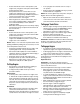
SECTION 1: IMPORTANT SAFE OPERATION PRACTICES WARNING: This symbol points out important safety instructions which, if not followed, could endanger the personal safety and/or property of yourself and others. Read and follow all instructions in this manual before attempting to operate this machine. Failure to comply with these instructions may result in personal injury. When you see this symbol—heed its warning.
5. 6. 7. 8. 9. 10. 11. 12. 13. 14. 15. 16. 17. 18. 19. 20. 2. Before cleaning, repairing, or inspecting machine disengage all control levers and stop the engine. Wait until the auger/impeller come to a complete stop. Disconnect the spark plug wire and ground against the engine to prevent unintended starting. 3. Check bolts and screws for proper tightness at frequent intervals to keep the machine in safe working condition. Also, visually inspect machine for any damage. 4.
SECTION 1: ASSEMBLING YOUR SNOW THROWER Unpacking • • • • • • Remove screws from the top sides and ends of the shipping crate. Set panel aside to avoid tire punctures or personal injury. Remove and discard plastic bag that covers unit. Remove any loose parts included with unit (i.e., Operator’s Manual, etc.). Roll unit out of crate. • Secure the upper handle and lower handle with the two plastic wing nuts, cupped washers and carriage bolts previously removed.
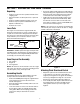
• Cable Plug the wire from the headlight into the alternator lead coming from the right side of the engine underneath the fuel tank. Cable Guide Alternator Lead Alternator Lead Discharge Chute Lamp Wire Figure 3 • NOTE: Wheels are omitted from illustration for clarity. If not already attached, unwrap the headlight wire which is attached to the headlight, beneath the handle panel. Wind the headlight wire around the lower right handle until excess slack is removed. See Figure 4.
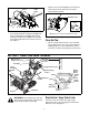
Chute Directional Control The drive control also locks the auger control so you can turn the chute directional control without interrupting the snow throwing process. If the auger control is engaged along with the drive control, the operator can release the auger control (on the left handle) and the augers will remain engaged. Release both controls to stop the augers and track drive. The chute directional control is located on left side of the snow thrower. See Figure 5.
Track Lock Lever Track Lock Lever The track lock lever is located on the right side of the snow thrower and is used to select the position of the auger housing and the method of track operation. Move the lever to the right, then forward or backward to one of the three positions. See Figure 6. Packed Snow Transport: Raises the front end of the snow thrower for easy transport. Using proper caution, this position may also be used on many gravel driveways to clear snow while leaving gravel undisturbed.
• • • • • • Rotate choke knob to FULL choke position (cold engine start). If engine is warm, place choke in OFF position instead of FULL. Push primer button two or three times for cold engine start, making sure to cover vent hole in primer button when pushing. DO NOT use primer to restart a warm engine after a short shutdown. Push starter button to start engine. When engine starts, release starter button, and move choke gradually to OFF.
Drift Cutters IMPORTANT: If the auger shows ANY signs of rotating, immediately return to the operator’s position and shut off the engine. Wait for ALL moving parts to stop before re-adjusting the auger control. • • • • Drift cutters should be used when operating the snow thrower in heavy drift conditions. On models so equipped, drift cutters are assembled to the auger housing inverted.
SECTION 4: MAKING ADJUSTMENTS WARNING: NEVER attempt to make any • adjustments while the engine is running, except where specified in the operator’s manual. Tip the snow thrower forward, allowing it to rest on the auger housing. See Figure 9. Frame Cover Chute Assembly The distance snow is thrown can be adjusted by changing the angle of the upper chute. Move the chute tilt control forward to decrease the distance, toward the rear to increase.
Shift Rod Adjustment Skid Shoes To adjust the shift rod, proceed as follows: The space between the shave plate and the ground can be adjusted. • • • • Remove the hairpin clip and slide the shift rod connector up, to separate the upper shift rod from the lower shift rod. See Figure 11. Place the shift lever into the sixth (6) position. Rotate the shift arm clockwise (from the operator’s position) as far as it will go.
WARNING: If any adjustments need to be made to the engine while the engine is running (e.g. carburetor), keep clear of all moving parts. Be careful of muffler, engine and other surrounding heated surfaces. To check the level of grease in the gear case, remove the vent plug. IMPORTANT: Do not overfill the gear case, since damage to the seals could result. Be sure the vent plug is free of grease in order to relieve pressure.
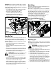
SECTION 6: SERVICING YOUR SNOW THROWER WARNING: Before servicing, repairing, or Carriage Bolt inspecting, disengage all controls and stop engine. Wait until all moving parts have come to a complete stop. Disconnect spark plug wire and ground it against the engine to prevent unintended starting. Always wear safety glasses during operation or while performing any adjustments or repairs. Shear Pin Cotter Pin Augers • • The augers are secured to the spiral shaft with six shear pins and cotter pins.
• • • • • Drive Belt Tip the snow thrower up and forward so that it rests on its auger housing. Refer to Figure 9. Remove the six self-tapping screws from the frame cover underneath the snow thrower. Roll the front and rear auger belts off the engine pulley. See Figure 17. Unhook the idler spring from the hex bolt on the auger housing. See Figure 18. Back out the stop bolt until the support bracket rests on the auger pulley. See Figure 19.
• • Using a 7/8" wrench to hold the shaft, loosen, but do not completely remove, the hex bolt and bell washer on the left end of gear shaft. See Figure 20. • Hex Bolt & Bell Washer Track Reassemble new friction wheel rubber to the friction wheel plates and hub, tightening the four screws in rotation and with equal force. Position the friction wheel assembly up onto the pin of the shift rod assembly, and slide the shaft through the assembly. Reassemble in reverse order.
SECTION 7: TROUBLESHOOTING Problem Engine fails to start Cause Remedy 1. Fuel tank empty, or stale fuel. 1. 2. 3. 4. 5. 6. 7. Blocked fuel line. Choke not in the ON position Faulty spark plug. Safety key not in ignition switch on engine. Spark plug wire disconnected. Primer button not being used properly. 2. 3. 4. 5. 6. 7. 1. 2. Unit running on CHOKE. Blocked fuel line or stale fuel. 1. 2. 3. Water or dirt in the fuel system. 3. Loss of power 1. 2. Spark plug wire loose.
SECTION 8: PARTS LIST FOR MODEL 730 STE 37 31 35 66 45 40 23 54 58 55 54 53 48 60 36 41 40 57 45 40 46 29 34 59 49 52 38 11 53 30 32 42 47 56 68 50 51 16 9 67 39 9 65 64 63 11 19 61 62 8 13 21 78 4 27 43 Part of handle panel for reference only 25 11 9 77 3 64 22 26 24 20 6 1 11 14 73 68 79 15 19 76 28 75 43 9 2 74 17 16 5 33 17 72 69 19 75 7 70 71 18 44 10 11 9 75 18 12
Model 730 STE Ref. No. 1. 2. 3. 4. 5. 6. 7. 8. 9. 10. 11. 12. 13. 14. 15. 16. 17. 18. 19. 20. 21. 22. 23. 24. 25. 26. 27. 28. 29. 30. 31. 32. 33. 34. 35. 36. 37. 38. 39. 40. Part No.
Model 730 STE 27 22 21 28 2 4 6 15 3 14 12 16 8 7 11 16 28 13 35 13 26 33 30 16 16 20 38 44 46 25 19 32 48 37 45 36 18 23 49 31 50 9 47 17 10 42 43 40 39 41 34 29 24 1 20 5
Model 730 STE Ref. No. 1. 2. 3. 4. 5. 6. 7. 8. 9. 10. 11. 12. 13. 14. 15. 16. 17. 18. 19. 20. 21. 22. 23. 24. 25. Part No. 714-04040 756-0178 784-5632B 710-0347 738-0281 736-0174 732-0611 712-3068 710-0642 711-04282 05931A 741-0309 710-0451 705-5226 684-04130A 712-04063 714-0161 715-04021 717-0528A 717-0526 731-2635 731-2643 718-04071 790-00087A 721-0325 Ref. No. Part Description Cotter Pin Flat Idler Auger Idler Arm Hex Cap Screw 3/8-16 x 1.
Model 730 STE 22 23 25 19 21 30 31 26 34 33 32 32 29 32 27 24 35 20 30 16 19 18 29 17 27 32 26 19 25 24 22 20 18 15 28 14 11 10 23 19 2 36 30 3 29 8 13 4 9 1 7 5 2 6 38 39 2 40 41 37 22 12 21
Model 730 STE Ref. No. 1. 2. 3. 4. 5. 6. 7. 8. 9. 10. 11. 12. 13. 14. 15. 16. 17. 18. 19. 20. 21. Part No. 784-5648 710-1652 748-0190 732-0264 712-0711 736-0105 684-0021 746-0898B 656-0012A 784-5689A 713-0413 746-0897 750-0997 711-1042 684-0042C 736-0160 714-0474 741-0563 736-0242 710-0538 710-0875 Ref. No. Part Description 22. 23. 24. 25. 26. 27. 28. 29. 30. 31. 32. 33. 34. 35. 36. 37. 38. 39. 40. 41. Frame Cover AB Screw 1/4-20 x.
Model 730 STE 44 45 54 1 50 51 47 46 2 54 42 41 56 51 56 53 55 52 3 48 46 5 4 49 9 11 6 10 8 30 12 7 37 16 36 19 13 38 20 26 15 17 23 33 29 22 31 25 30 33 19 21 24 22 26 37 28 20 14 39 27 34 18 40 35 32 21 16 18 15 17 14 24 13 32
Model 730 STE Ref. No. 1. 2. 3. 4. 5. 6. 7. 8. 9. 10. 11. 12. 13. 14. 15. 16. 17. 18. 19. 20. 21. 22. 23. 24. 25. 26. 27. 28. Part No. 720-0223 710-0604A 784-5642 710-0157 736-0242 684-0038 710-0459A 712-0214 748-0353A 750-0547 784-5609 684-0009 712-0346 731-1292 736-0272 731-1538A 631-0032 750-0995 738-0140 736-0406 750-0909 712-04063 618-0044 684-0024 710-1231 784-5639 711-0911 713-0233 Ref. No. Part Description Grip Tap Screw, 5/16-18 x.625 Track Lockout Plate Hex Cap Screw, 5/16-24 x.
Model 730 STE 1 17 2 26 27 IMPORTANT: For a proper working machine, use Factory Approved Parts. V-BELTS are specially designed to engage and disengage safely. A substitute (non OEM) V-Belt can be dangerous by not disengaging completely 3 4 9 8 4 7 11 10 16 19 12 15 6 5 16 19 16 21 16 22 13 23 14 18 24 25 20 Ref. No. 1. 2. 3. 4. 5. 6. 7. 8. 9. 10. 11. 12. 13. 14. Part No.
MANUFACTURER’S LIMITED COMMERCIAL WARRANTY FOR: The limited warranty set forth below is given by Cub Cadet LLC with respect to new merchandise used for commercial purposes and purchased and used in the United States and/ or its territories and possessions, and by MTD Products Limited with respect to new merchandise purchased and used in Canada and/or its territories and possessions (either entity respectively, “Cub Cadet”). c. d. e.
MANUFACTURER’S LIMITED WARRANTY FOR: The limited warranty set forth below is given by Cub Cadet LLC with respect to new merchandise purchased and used in the United States, its possessions and territories, and by MTD Products Limited with respect to new merchandise purchased and used in Canada and/or its territories and possessions.