OPERATOR’S MANUAL SNOW THROWER MODEL 31AH4Q3G100 4-Wheel Drive IMPORTANT: READ SAFETY RULES AND INSTRUCTIONS CAREFULLY Warning: This unit is equipped with an internal combustion engine and should not be used on or near any unimproved forestcovered, brush-covered or grass-covered land unless the engine’s exhaust system is equipped with a spark arrester meeting applicable local or state laws (if any). If a spark arrester is used, it should be maintained in effective working order by the operator.
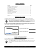
TABLE OF CONTENTS Content Page Important Safe Operation Practices................................................................... 3 Assembling Your Snow Thrower ....................................................................... 5 Know Your Snow Thrower ................................................................................. 7 Operating Your Snow Thrower .......................................................................... 8 Making Adjustments .........................................
SECTION 1: IMPORTANT SAFE OPERATION PRACTICES WARNING: This symbol points out important safety instructions which, if not followed, could endanger the personal safety and/or property of yourself and others. Read and follow all instructions in this manual before attempting to operate this machine. Failure to comply with these instructions may result in personal injury. When you see this symbol - heed its warning.
3. 4. 5. 6. 7. 8. 9. 10. 11. 12. 13. 14. 15. 16. 17. 18. 19. 20. The clutch levers must operate easily in both directions and automatically return to the disengaged position when released. Never operate with a missing or damaged discharge chute. Keep all safety devices in place and working. Never run an engine indoors or in a poorly ventilated area. Engine exhaust contains carbon monoxide, an odorless and deadly gas. Do not operate machine while under the influence of alcohol or drugs.
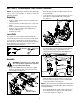
SECTION 2: ASSEMBLING YOUR SNOW THROWER NOTE: Any reference in this manual to the left or right side of the snow thrower is observed from the operator’s position. • • Unpacking • • • • • Raise the upper handle assembly until it locks over the lower handle. Look at lower rear of snow thrower frame to be sure both cables are aligned with cable roller guides. See Figure 3. Remove staples from the top sides and ends of the shipping crate. Set panel aside to avoid tire punctures or personal injury.
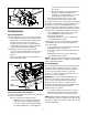
snow thrower, the machine should otherwise move freely. b. Engage the traction control and attempt to move the machine both forward and rearward. You should experience resistance as the wheels should not be turning. • Move the shift lever into the fast reverse (R2) position and repeat the previous steps (a & b).
• • Retighten the hex nuts loosened earlier. Repeat this adjustment on the skid shoe found on the opposite side of the snow thrower. Tire Pressure The tires are overinflated for shipping purposes. • Check tire pressure, by referring to tire sidewalls for recommended tire pressure. NOTE: If the tire pressure is not equal in all tires, the unit may pull to one side or the other. Skid Shoes WARNING: Maximum tire pressure under any circumstance is 30 psi.
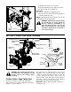
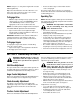
Auger Drive Control To change the direction in which discharged snow is thrown, proceed as follows: • Push the toggle switch to the left to rotate the chute counterclockwise. • Push the toggle switch to the right to rotate the chute clockwise. The auger drive control is located on the left handle. Squeeze the control grip to engage the augers. Release to stop the snow throwing action. (Traction control must also be released.) See Figure 8.
WARNING: Use extreme care when handling gasoline. Gasoline is extremely flammable and the vapors are explosive. Never fuel machine indoors or while the engine is hot or running. Extinguish cigarettes, cigars, pipes an other sources of ignition. • • • • • A plastic cup is provided inside the fuel fill opening on the fuel tank. Remove and discard this cup before filling up the tank. Use the separate fuel tank cap to close after fill-up.
NOTE: Keep it in a safe place. Engine will not start without ignition key. • Release both the auger control and the traction control, if engaged. The auger control can be locked so you can turn the electric chute directional control without interrupting the snow throwing process. Wipe all snow and moisture from the carburetor cover in the area of the control levers. Also, move control levers back and forth several times.
IMPORTANT: Make certain to check for correct adjustment of the shift rod as instructed under Final Adjustments in the Assembly Section, before operating the snow thrower.
Electric Chute-Rotation Motor Do not overfill the gear case. Damage to the seals could result. Be sure the vent plug is free of grease in order to relieve pressure. The gear on the electric chute-rotation motor and the base of the discharge chute itself should be lubed with multi-purpose automotive grease once a season. See Figure 11. Auger Shaft At least once a season, remove the shear bolts on the auger shaft. Spray lubricant inside the shaft.
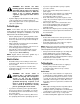
Self-Tapping Screw Remove Belt Remove Belt Idler Pulley Belt Cover Figure 13 • Remove the three hex nuts and lock washers which attach the auger housing assembly to the frame assembly on each side. See Figure 14. Figure 15 WARNING: Do not attempt to change the auger belt without the help of an assistant. It is very important that one person, standing at the operating position, firmly hold the snow thrower housing to prevent it from tipping while the other person replaces the belt.
• • • • • Remove the plastic belt cover on the front of the engine by removing the two self-tapping screws. Tip the snow thrower up and forward, so that it rests on the housing. Remove six self-tapping screws from the frame cover underneath the snow thrower. Pull the idler pulley away from the drive belt and remove the belt from the engine pulley. Working from the underside of the frame, slip belt between the friction wheel and the friction wheel disc.
• • • • Reassemble new friction wheel rubber to the friction wheel assembly, tightening the six screws in rotation and with equal force. Insert the pin from the shift arm assembly into the friction wheel assembly and hold assembly in position. Refer to Figure 18. Slide the gear shaft through the left side of the housing and through the friction wheel assembly. Insert the gear shaft through the sprocket and the spacer. Make certain that the chain engages both the large and the small sprocket.
SECTION 8: TROUBLE SHOOTING GUIDE Trouble Possible Cause(s) Engine fails to start 1. Corrective Action Fuel tank empty, or stale fuel. 1. Blocked fuel line. Choke not in the ON position Faulty spark plug. Safety key not in ignition switch on engine. Spark plug wire disconnected. Primer button not being used properly. Fuel shut-off valve closed. 2. 3. 4. 5. Fill tank with clean, fresh gasoline. Fuel becomes stale after thirty days. Clean the fuel line.
Model H4Q3G 1 17 6 8 14 13 9 6 18 14 6 8 14 16 7 8 2 15 13 12 3 10 4 23 8 14 19 16 22 2 Ref. No. 1. 2. 3. 4. 5. 6. 7. 8. 9. 10. 12. 13. 14. 15. 16. 17. 18. 19. 20. 21. 22. 23. Part No. 710-0459A 710-0599 712-0116 713-0491 713-0600 714-0161 736-0235 736-0351 737-0170 737-3000 738-1135A 738-1136A 741-0598 756-0313 784-0400A 784-0401A 618-0420A 618-0421A 634-0195 734-1732 734-1735 741-0401 734-0255 Description 21 20 Special Hex Screw: 3/8-24 x 1.5” TT Screw: 1/4-20 x 0.
Model H4Q3G 29 9 30 5 25 22 39 27 3 6 20 17 1 18 13 18 13 22 14 10 23 2 16 18 19 4 22 6 12 60 35 7 22 6 59 15 36 22 13 22 28 38 31 33 11 21 28 21 26 40 8 32 44 51 33 49 53 56 48 41 54 45 46 50 57 43 47 52 42 55 43 18 23 34 10
Model H4Q3G Ref. No. 1. 2. 3. 4. 5. 6. 7. 8. 9. 10. 11. 12. 13. 14. 15. 16. 17. 18. 19. 20. 21. 22. 23. 25. 26. 27. 28. 29. 30. Part No. 05931A 684-0065 705-5226 710-0451 710-0459A 710-0604A 710-0703 710-0890A 712-0116 712-0324 712-0429 712-0798 712-3010 712-3068 715-0114 731-1379C 732-0611 736-0119 736-0169 736-0167 736-0188 736-0242 736-0463 738-0281 741-0245 741-0309 741-0493A 756-0178 784-5632A Description Bearing Housing Impeller Assy. 12” dia. Chute Reinforcement Carriage Bolt 5/16-18 x .75” Gr.
Model H4Q3G 43 44 42 54 48 13 37 13 50 9 48 37 4 49 56 15 27 39 18 32 59 16 38 33 47 2 52 11 7 22 33 39 40 46 40 33 20 23 8 25 16 19 22 33 38 60 21 31 6 14 41 34 24 34 45 28 23 39 1 3 11 32 55 18 13 17 29 57 41 51 10 15 5 12 11 13 48 53 13 20 37 16 30 23
Model H4Q3G Ref. No. 1. 2. 3. 4. 5. 6. 7. 8. 9. 10. 11. 12. 13. 14. 15. 16. 17. 18. 19. 20. 21. 22. 23. 24. 25. 27. 28. 29. 30. 31. 32. 33. 34. Part No. 618-0043 618-0044 618-0303A 618-0420A 618-0421A 656-0012A 684-0014B 684-0042C 684-0130 684-0131A 710-0599 710-0788 710-1652 711-1267 711-1268 711-1364 712-0711 712-3017 713-0602 713-0233 713-0413 713-0473 714-0104 714-0474 716-0102 732-0209 732-0264 736-0105 736-0142 736-0160 736-0169 736-0351 736-0626 Ref. No. 37. 38. 39. 40. 41. 42. 43. 44. 45. 46. 47.
Model H4Q3G 29 30 7 31 10 28 27 3 11 26 14 20 25 2 21 23 23 8 18 3 21 13 23 15 5 1 9 6 12 22 16 4 19 24 22
Model H4Q3G Ref. No. 1. 2. 3. 4. 5. 6. 7. 8. 9. 10. 11. 12. 13. 14. 15. Part No. 05896A 710-0230 710-0627 710-0654A 710-0696 710-1245A 710-1652 710-3005 712-0181 731-1324 732-0710 736-0242 736-0247 736-0270 736-0331 Description Idler Bracket Hex Bolt 1/4-28 x 0.5” Gr.5 Hex Scr w/ Patch: 5/16-24 x 0.75” Hex Washer Head Sems Screw Hex Bolt 3/8-24 x .875” Gr.8 Hex Scr w/ Patch: 5/16-24 x .875” Hex Washer Head TT Hex Screw: 3/8-16 x 1.
68 Model H4Q3G 57 58 27 57 58 55 65 72 70 53 73 72 27 69 82 71 27 68 80 74 63 59 67 58 69 27 56 64 66 77 60 66 62 81 76 78 58 54 31 45 79 11 83 75 61 29 9 15 51 40 13 46 37 13 47 5 8 2 5 14 24 17 20 22 10 14 21 3 50 11 9 40 18 16 41 12 4 25 26 1 42 31 43 9 11 27 15 19 35 39 14 35 85 38 52 84 36 86 48 10 7 23 49 For Reference Only For Reference Only 87 44 88 32 28 30 24
Model H4Q3G Ref. No. Part No. Ref. No. Part Description Part No. Part Description 1. 684-0008A Shift Arm Assembly 47. 746-0901 Control Cable 2. 710-0262 Carriage Bolt 5/16-18 x 1.5” 48. 741-1140 Bushing 3. 710-0449 Carriage Bolt 5/16-18 x 2.25” 49. 784-5745 Motor Bracket 4. 710-0788 TT Screw 1/4-20 x 1” 50. 784-5594 Cable Bracket 5. 710-0837 C-Sunk Screw #10-16x 0.625” 51. 784-5604 Handle: Chute Tilt 7. 710-1880 Hex Screw 5/16-18 x .75” 52.
Notes 26
MANUFACTURER’S LIMITED WARRANTY FOR: TWO-YEAR RESIDENTIAL ONE-YEAR COMMERCIAL Proper maintenance of your Cub Cadet equipment is the owner’s responsibility. Follow the instructions in your operator’s manual for correct lubricants and maintenance schedule. Your Cub Cadet dealer carries a complete line of quality lubricants and filters for your equipment’s engine, transmission, chassis and attachments.