Safe Operation Practices • Set-Up • Operation • Maintenance • Service • Troubleshooting • Warranty Operator’s Manual Two Stage Snow Thrower — Models 930 SWE & 933 SWE WARNING READ AND FOLLOW ALL SAFETY RULES AND INSTRUCTIONS IN THIS MANUAL BEFORE ATTEMPTING TO OPERATE THIS MACHINE. FAILURE TO COMPLY WITH THESE INSTRUCTIONS MAY RESULT IN PERSONAL INJURY. CUB CADET LLC, P.O. BOX 361131 CLEVELAND, OHIO 44136-0019 Printed In USA FORM NO.
1 To The Owner Thank You Thank you for purchasing a Snow Thrower manufactured by Cub Cadet. It was carefully engineered to provide excellent performance when properly operated and maintained. If applicable, the power testing information used to establish the power rating of the engine equipped on this machine can be found at www.opei.org or the engine manufacturer’s web site. Please read this entire manual prior to operating the equipment.
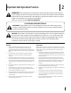
Important Safe Operation Practices 2 WARNING! This symbol points out important safety instructions which, if not followed, could endanger the personal safety and/or property of yourself and others. Read and follow all instructions in this manual before attempting to operate this machine. Failure to comply with these instructions may result in personal injury. When you see this symbol.
Safe Handling of Gasoline 5. To avoid personal injury or property damage use extreme care in handling gasoline. Gasoline is extremely flammable and the vapors are explosive. Serious personal injury can occur when gasoline is spilled on yourself or your clothes which can ignite. Wash your skin and change clothes immediately. Never run an engine indoors or in a poorly ventilated area. Engine exhaust contains carbon monoxide, an odorless and deadly gas. 6.
Clearing a Clogged Discharge Chute Hand contact with the rotating impeller inside the discharge chute is the most common cause of injury associated with snow throwers. Never use your hand to clean out the discharge chute. To clear the chute: 1. SHUT THE ENGINE OFF! 2. Wait 10 seconds to be sure the impeller blades have stopped rotating. 3. Always use a clean-out tool, not your hands. Maintenance & Storage 1. Never tamper with safety devices. Check their proper operation regularly.
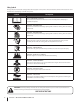
Safety Symbols This page depicts and describes safety symbols that may appear on this product. Read, understand, and follow all instructions on the machine before attempting to assemble and operate. Symbol Description READ THE OPERATOR’S MANUAL(S) Read, understand, and follow all instructions in the manual(s) before attempting to assemble and operate WARNING— ROTATING BLADES Keep hands out of inlet and discharge openings while machine is running.
3 Assembly & Set-Up Contents of Carton • One Snow Thrower • Two Replacement Auger Shear Pins • One Product Registration Card • One Snow Thrower Operator’s Manual • One Engine Operator’s Manual • One Chute Assembly Assembly IMPORTANT: Two replacement auger shear pins are included with this manual (or stowed in the plastic handle panel). Refer to the Maintenance section for more information regarding shear pin replacement.
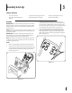
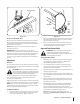
Chute Assembly 1. 6. Loosen, but do not remove, the chute crank bracket in order to attached the chute assembly. See Figure 3-3. Check that the chute cables are properly routed through the cable guide on top of engine shroud. See Figure 3-5. Chute Crank Bracket Figure 3-5 Figure 3-3 2. Remove lock nuts and screws securing one of the flange keepers to the chute assembly. Loosen the fasteners of the other two flange keepers. See Figure 3-3. 3.
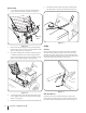
Clean-out Tool Lower Shave Plate Shave Plate Raise Shave Plate Figure 3-8 Figure 3-7 Tire Pressure (Pneumatic Tires) 2. The tires can be over-inflated for shipping purposes. Check the tire pressure before operating the snow thrower. Refer to the tire side wall for manufactures’s recommended psi and deflate or inflate the tires as necessary. While observing the distance between the shave plate and the ground, adjust the skids shoes up or down to achieve the desired shave plate height. 3.
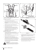
Speed Selector Lever Chute Tilt Control Auger Control Drive Control Drive Control Cable Auger Control Cable Rearward most hole of the actuator brackets Figure 3-9 Figure 3-10 Testing Drive Control & Shift Lever 1. With the engine turned off, move the speed selector lever into sixth (6) position. Refer to Figure 3-9. 2. With the wheel drive control released, push the snow thrower forward, then pull it back. The machine should move freely. 3.
4 Controls and Features Wheel Drive Control Headlight Speed Selector Lever Two Way Chute Pitch Control™ Auger Control Wheel Steering Control Chute Directional Control Chute Assembly Clean-Out Tool Augers Skid Shoe NOTE: For detailed information on all engine controls, refer to the separate Engine Operator’s Manual supplied with this unit. Speed Selector Lever The speed selector lever is located in the right side of the handle panel and is used to determine ground speed and direction of travel.
Auger Control • Move the lever rearward to pivot the upper chute upward and increase the distance snow is thrown. CHUTE DIRECTIONAL CONTROL DISCHARGE LEFT DISCHARGE RIGHT • CHUTE TILT DOWN CHUTE TILT UP The auger control is located on the left handle. Squeeze the control grip against the handle to engage the augers and start snow throwing action. Release to stop.
Wheel Steering Controls The left and right wheel steering controls are located on the underside of the handles. Squeeze the right control to turn right; squeeze the left control to turn left. NOTE: Operate the snow thrower in open areas until you are familiar with these controls. Chute Clean-Out Tool WARNING! Never use your hands to clear a clogged chute assembly. Shut off engine and remain behind handles until all moving parts have stopped before unclogging.
5 Operation Starting and Stopping the Engine Replacing Shear Pins Refer to the Engine Operator’s Manual packed with your snow thrower for instructions on starting and stopping the engine. Each of the auger spiral assemblies are secured to the spiral shaft with a shear pin and cotter pin. If the auger should strike a foreign object or ice jam, the snow thrower is designed so that the pins may shear. If the augers will not turn, check to see if the pins have sheared. See Figure 5-1. To Engage Drive 1.
6 Maintenance & Adjustments Maintenance 3. WARNING! Before servicing, repairing, lubricating, or inspecting, disengage all controls and stop engine. Wait until all moving parts have come to a complete stop. Remove the ignition key, disconnect the spark plug wire and ground it against the engine to prevent unintended starting. Always wear safety glasses during operation or while performing any adjustments or repairs. 4.
Chute Directional Control Once a season, lubricate the eye-bolt bushing and the spiral with 3-in-1 oil. Auger Shaft At least once a season, one at a time, remove the shear pins from the auger shaft. Spray lubricant inside the hub of each auger spiral assembly and around the spacers on the auger shaft. See Figure 6-3. Shear Pins Vent Plug Grease Fitting Figure 6-4 1. 2. 3. 4. Bow-Tie Pins Spacers Figure 6-3 Grease fittings can also be found at each end of the auger shaft.
Drive Control 4. If there is no friction wheel clearance when the drive control is disengaged, or the friction wheel does not solidly contact the drive friction plate when the drive control is engaged, re-adjust the lock nut on the lower end of the drive cable following the instructions in the Assembly & Set-Up . 5. Reassemble the frame cover. Refer to “Auger and Drive Control Cables” of the Assembly & Set-Up - 3 for instructions to adjust the drive control.
7 Service Belt Replacement Belt Removal Preparation 1. Remove Remove the chute crank rod from the chute crank assembly by removing the hair pin clip shown in Figure 7-1. Move the chute crank rod away from the assembly as shown. Loosen Figure 7-3 Auger Belt Replacement To remove and replace your snow thrower’s auger belt, proceed as follows: 1. Figure 7-1 2. Remove the plastic belt cover on the front of the engine by removing the three self-tapping screws. See Figure 7-2.
3. Pull the brake bracket assembly towards the cable guide roller and unhook the auger cable “Z” fitting. Refer to Figure 7-5. 7. Lift the brake bracket assembly out of the pulley groove and slide the pulley assembly off the posts of the auger pulley adapter to remove the old belt. Refer to Figure 7-7. Adapter Post B C z-fitting A Figure 7-5 4. From both sides of the frame assembly, use a 1/2" wrench to remove the three hex tap screws securing the transmission frame to the auger housing assembly.
NOTE: To adjust, disconnect ferrule from brake bracket assembly. Thread ferrule in (towards idler) to increase tension on belt, or out to decrease belt tension. NOTE: The brake puck must always be firmly seated in the pulley groove when auger control is disengaged. CAUTION: Repeat the “Testing Auger Drive Control” from the Assembly & Set-up section before operating the snow thrower. 14. Re-install the belt cover.
5. 6. 7. Holding the friction wheel assembly, slide the hex shaft out of the right side of the frame. The spacer on the left side of the hex shaft will fall and the sprocket should remain hanging lose in the chain. Lift the friction wheel assembly out between the axle shaft and the drive shaft assemblies. Remove four screws securing the friction wheel to the hub assembly (refer to Figure 7-11). Discard old friction wheel. Figure 7-11 8.
Off-Season Storage If the snow thrower will not be used for 30 days or longer, the equipment needs to be stored properly. Follow storage instructions below to ensure top performance from the snow thrower for many more years. Short-Term Storage It is important to prevent gum deposits from forming in essential fuel system parts of the engine such as the carburetor, fuel filter, fuel hose, or tank during short-term storage (15-30 days). To prevent this, treat the fuel system using a fuel stabilizer.
8 Troubleshooting Problem Cause Remedy Excessive vibration 1. Loose parts or damaged auger. 1. Stop engine immediately and disconnect spark plug wire. Tighten all bolts and nuts. If vibration continues, have unit serviced by an authorized Service Center. Loss of power 1. Spark plug wire loose. 1. Connect and tighten spark plug wire. 2. Gas cap vent hole plugged. 2. Remove ice and snow from gas cap. Be certain vent hole is clear. 1. Drive control cable in need of adjustment. 1.
9 Replacement Parts Component 24 Part Number and Description 929-0071A Extension Cord, 110V 954-04194A 954-04202 Auger Drive Belt Wheel Drive Belt 918-04178 718-04034 Friction Wheel Assembly Friction Wheel w/Bonded Rubber 725-05326 Lamp 738-04155 714-04040 Shear Pin Bow-tie Cotter Pin 731-07032 Slide Shoe, Deluxe 931-2643 Chute Clean-out Tool 784-5715B 784-5714B Shave Plate, 30-inch Shave Plate, 33-inch 731-05632 Key 951-10292 Spark Plug Phone (800) 965-4CUB (4282) to order replacemen
10 Attachments & Accessories The following attachments and accessories are available for your Cub Cadet 900 series snow thrower. See your Cub Cadet dealer or the retailer from which you purchased your snow thrower for information regarding price and availability.
Notes 26 11
Section 11 — Notes 27
CUB CADET LLC MANUFACTURER’S LIMITED WARRANTY FOR SNOW THROWERS, LOG SPLITTERS CHIPPER-SHREDDERS, CHIPPER-SHREDDER VACUUMS AND JET SWEEPS The limited warranty set forth below is given by Cub Cadet LLC with respect to new merchandise purchased and used in the United States, its possessions and territories, and by MTD Products Limited with respect to new merchandise purchased and used in Canada and/or its territories and possessions. a.