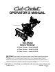
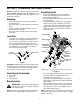
OPERATOR’S MANUAL 33” Model Shown Two Stage Snow Thrower 28" Snow Thrower — Model 928 SWE 33" Snow Thrower — Model 933 SWE 45" Snow Thrower — Model 945 SWE IMPORTANT: Read safety rules and instructions carefully before operating equipment Warning: This unit is equipped with an internal combustion engine and should not be used on or near any unimproved forestcovered, brush-covered or grass-covered land unless the engine’s exhaust system is equipped with a spark arrester meeting applicable local or state l
TABLE OF CONTENTS Content Customer Support Important Safe Operation Practices Assembling Your Snow Thrower Knowing Your Snow Thrower Operating Your Snow Thrower Making Adjustments Maintaining Your Snow Thrower Page 2 3 5 8 9 11 13 Content Servicing Your Snow Thrower Off-Season Storage Trouble Shooting Illustrated Parts List Commercial Warranty Residential Warranty Page 15 18 19 20 31 32 FINDING MODEL NUMBER This Operator’s Manual is an important part of your new snow thrower.
SECTION 1: IMPORTANT SAFE OPERATION PRACTICES WARNING: This symbol points out important safety instructions which, if not followed, could endanger the personal safety and/or property of yourself and others. Read and follow all instructions in this manual before attempting to operate this machine. Failure to comply with these instructions may result in personal injury. When you see this symbol—heed its warning.
6. 7. 8. 9. 10. 11. 12. 13. 14. 15. 16. 17. 18. 19. 20. Maintenance And Storage Do not operate machine while under the influence of alcohol or drugs. Muffler and engine become hot and can cause a burn. Do not touch. Exercise extreme caution when operating on or crossing gravel surfaces. Stay alert for hidden hazards or traffic. Exercise caution when changing direction and while operating on slopes. Plan your snow throwing pattern to avoid discharge towards windows, walls, cars etc.
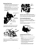
SECTION 2: ASSEMBLING YOUR SNOW THROWER NOTE: This Operator’s Manual covers several models. Snow thrower features vary by model. Not all features discussed in this manual are applicable to all snow thrower models. Assembling Handle Unpacking • • • • • • • • Remove staples from the top, sides, and ends of the shipping crate. Set panels aside to avoid tire punctures or personal injury. Remove and discard plastic bag that covers unit. Roll the unit out of the crate.
Attaching Chute Crank • • Engine Alternator Lead Remove the internal cotter pin from the upper chute crank. Slide the upper chute crank through the upper chute crank bracket and into the sleeve on the lower chute crank. Align the hole in the upper chute crank with the hole in the sleeve (If necessary, use a pair of pliers to assist in aligning holes). Insert the internal cotter pin through the holes to secure the chute crank. See Figure 3.
• • If you experienced resistance rolling the unit, either when repositioning the shift lever from 6 to R2 or when attempting to move the machine with the drive control released, adjust the drive control immediately. See Adjusting Wheel Drive and Auger Drive Controls. Reattach the spring to the actuator bracket. Repeat the wheel drive and auger control tests to verify proper adjustment. Repeat previous steps if necessary to attain proper adjustment of each cable.
SECTION 3: KNOWING YOUR SNOW THROWER WARNING: Be familiar with all the controls on the snow thrower and their proper operation. Know how to stop the machine and disengage them quickly. Compare Figure 9 below with your equipment and be familiar with its controls before starting it.
Chute Crank Skid Shoe The chute crank is located on the left side of the snow thrower. Use it to change the direction in which snow is thrown. Avoid directing at persons, animals, cars and buildings. The skid shoe position is normally determined by the surface from which snow has to be removed. Loose surfaces (e.g. gravel or stone) require raising the snow thrower by adjusting the skid shoe to a lower position. Adjust accordingly.
• • • • • • If your home electrical system is grounded, but a three-hole receptacle is not available, one should be installed by a licensed electrician before using the electric starter. If you have a grounded three-prong receptacle, proceed as follows: Connect power cord to switch box on engine. Plug the other end of power cord into a three-hole, grounded 120 volt AC receptacle. Rotate choke knob to ON position. Push primer button three times, making sure to cover vent hole when pushing.
Chute Clean-Out Tool The chute clean-out tool is conveniently fastened to the rear of the auger housing with a mounting clip. Never use your hand to clean a clogged chute or chute opening; use this clean-out tool instead. • • • • • • Chute Clean-Out Tool Clip Release both the wheel drive control and the auger drive control levers. Stop the engine by removing the ignition key. Remove the chute clean-out tool from the clip which secures it to the rear of the auger housing. See Figure 10.
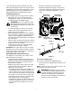
Wheel Drive Control Chute Assembly If you are uncertain about correct adjustment, proceed as follows: • Drain the gasoline out of your snow thrower’s engine, and place a piece of plastic film under the gas cap to avoid spillage. • Tip the snow thrower forward, allowing it to rest on the auger housing. • Remove the frame cover underneath the snow thrower by removing six self-tapping screws. • Locate the opening between the axle support bracket and the front frame support (See Figure 12).
SECTION 6: MAINTAINING YOUR SNOW THROWER WARNING: Before lubricating, repairing, or inspecting, disengage all clutch levers and stop engine. Wait until all moving parts have come to a complete stop. Disconnect the spark plug wire and ground it against the engine to prevent unintended starting. Shear Pins Vent Plug Bearing General Recommendations • • • • Always observe safety rules when performing any maintenance.
Wheel Drive Control / Auger Control Lock • The cams on the ends of the control rods which interlock the wheel drive and auger drive controls must be lubricated at least once a season or every 25 hours of operation using a multi-purpose automotive grease. The cams can be accessed from beneath the handle panel. See Figure 16. • • Handle Panel • • Remove the six self-tapping screws from the frame cover underneath the snow thrower.
SECTION 7: SERVICING YOUR SNOW THROWER WARNING: Before servicing, repairing, or inspecting, disengage all clutch levers and stop engine. Wait until all moving parts have come to a complete stop. Disconnect spark plug wire and ground it against the engine to prevent unintended starting. Shave Plate Carriage Bolts Augers The auger spirals are secured to the auger shaft with shear pins and bowtie cotter pins. If you hit a foreign object or ice jam, the snow thrower is designed so that the pins may shear.
• • Remove the large shoulder bolt and washer on the left hand side of the engine pulley. See Figure 19. Engine Pulley Place the new auger belt in the pulley groove. Position the pulley and belt inside the belt keepers on the rear of the auger housing. See Figure 21.
Drive Belt • • • • • Repeat the first five steps from the above "Auger Belt" sub-section to split the snow thrower. Pull the idler pulley away from the backside of the drive belt to relieve the tension and slide the drive belt off the idler pulley (If necessary unhook the extension spring from the belt cover plate). See Figure 22. Roll the drive belt off the lower drive pulley and remove the belt from the engine pulley.
• • • Remove the four hex tapp screws securing the friction wheel to the bearing/extrusion plate assembly. See Figure 25. With its recessed face toward the extrusion plate, position the new friction wheel so that its four screw holes align with the extrusion plate holes; then push the friction wheel onto the hub of the bearing/ extrusion plate assembly. See Figure 25. Secure the friction wheel with the four hex tap screws. Torque the screws to 6-9 ft-lbs. .
SECTION 9: TROUBLESHOOTING Problem Cause Remedy Engine fails to start. 1. 2. 3. 4. 5. 6. 7. Fuel tank empty, or stale fuel. Blocked fuel line. Choke not in ON position Faulty spark plug. Safety key not in ignition switch on engine. Spark plug wire disconnected. Primer button not being used properly. 1. 2. 3. 4. 5. 6. 7. Fill tank with fresh gasoline. Clean the fuel line. Move switch to ON position Clean, adjust gap or replace. Insert the key fully into the switch. Connect spark plug wire.
SECTION 10: ILLUSTRATED PARTS LISTS 22 12 19 4 20 41 50 24 11 48 53 55 37 30 21 43 52 57 35 21 38 37 43 9 29 21 36 21 11 34 52 18 51 54 38 16 33 6 15 21 38 47 59 14 8 39 21 21 56 2 63 58 27 13 49 16 15 46 38 61 14 10 21 27 32 62 49 44 66 40 21 31 64 28 65 26 42 44 3 42 45 32 17 27 49 32 8 11 5 38 51 1 38 49 9 25 60 27 49 49 39 44 2 31 7 44 32 7 20 46 23
REF. PART NO. NUMBER 1 2 3 4 5 6 9 05244A 05845C 618-0257 618-0281A 684-0090A 684-0164A 684-0166A 684-0155A 684-04151 684-04151 684-04152 684-04152 710-0371 10 11 12 13 710-04527 710-0451 710-0459A 710-0528 14 710-0604A 15 710-1260A 16 17 18 19 20 710-3008 710-04526 711-0640 711-0677 712-0116 21 22 23 24 25 26 27 712-04063 712-0717 712-04102 714-0104 714-0126 714-0135 714-04040 714-04040 715-0118 725-0157 731-1696A 731-05162 731-05163 7 8 28 29 30 31 32 33 34 REF. PART QTY. NO.
16 9 62 17 82 82 63 17 77 78 74 62 11 52 58 13 38 48 15 18 17 14 26 49 17 71 46 7 50 60 42 17 37 36 3 36 46 43 66 61 24 6 46 33 46 4 15 54 5 28 29 25 75 58 27 64 43 52 51 61 21 32 69 10 19 76 48 47 48 59 18 29 15 13 57 13 27 56 54 28 8 61 60 50 26 49 22 55 38 61 39 20 67 34 68 12 32 73 70 23 32 66 2 53 65 41 35 40 34 21 8 47 22 1 44 31 82 72 31 44 78 45 30 17 17 79 80 NOTE: Please add the applicable color code below to the pa
REF. PART NO.
27 9 1 24 37 25 10 4 39 21 13 5 16 7 26 30 33 16 30 15 20 10 38 32 2 8 17 14 13 31 6 23 41 30 33 19 22 2 28 7 36 19 11 18 30 22 35 8 40 12 28 19 3 31 28 23 11 28 19 12 29 24 34
REF. PART NO.
25 27 26 10 24 14 14 4 4 14 3 1 13 18 23 7 17 8 13 5 22 9 15 12 12 16 19 11 6 20 21 2 26
REF. PART NO. NUMBER 1 2 3 4 DESCRIPTION 7 8 9 10 11 12 13 Bracket, Belt Cover ..................... Screw, Hex Cap, 3/8-14 x 1.25 GR8 Screw, Hx Cap, 5/16-24 x .625 GR5 Screw, Hx Wash Hd Tapp, .......... 5/16-18 x .5 710-0672 Screw, Hx Cap — 28" S.T. Only — 5/16-24 x 1.25 GR5 710-1245B Screw, Hx Cap — 33" and 45" S.T. Only — 5/16-24 x .875 GR8 710-1008 Screw, Hx Sems Tapp — 28" S.T. Only — 3/8-16 x 1.875 710-0502 Screw, Hx Sems Tapp — 33" and 45" S.T. Only — 3/8-16 x 1.
14 29 6 36 11 26 6 30 31 30 21 6 35 38 29 9 14 34 19 22 37 13 1 10 11 20 23 26 22 4 8 25 11 33 18 ‘B’ 11 ‘A’ ‘A’ ‘B’ 27 7 28 32 15 18 11 24 17 3 8 2 12 16 16 5 28
REF. PART NO.
MANUFACTURER’S LIMITED COMMERCIAL WARRANTY FOR: The limited warranty set forth below is given by LLC with respect to new merchandise used for commercial purposes and purchased and used in the United States and/or its possessions and territories, and by MTD Products Limited with respect to new merchandise purchased and used in Canada and/or its territories and possessions (either entity respectively, “Cub Cadet”).
MANUFACTURER’S LIMITED WARRANTY FOR: The limited warranty set forth below is given by Cub Cadet LLC with respect to new merchandise purchased and used in the United States, its possessions and territories, and by MTD Products Limited with respect to new merchandise purchased and used in Canada and/or its territories and possessions.