Safe Operation Practices • Set-Up • Operation • Maintenance • Service • Troubleshooting • Warranty Operator’s Manual Two Stage Snow Thrower — Models 930 SWE & 933 SWE WARNING READ AND FOLLOW ALL SAFETY RULES AND INSTRUCTIONS IN THIS MANUAL BEFORE ATTEMPTING TO OPERATE THIS MACHINE. FAILURE TO COMPLY WITH THESE INSTRUCTIONS MAY RESULT IN PERSONAL INJURY. CUB CADET LLC, P.O. BOX 361131 CLEVELAND, OHIO 44136-0019 Printed In USA FORM NO.
1 To The Owner Thank You Thank you for purchasing a Snow Thrower manufactured by Cub Cadet LLC. It was carefully engineered to provide excellent performance when properly operated and maintained. Please read this entire manual prior to operating the equipment. It instructs you how to safely and easily set up, operate and maintain your machine. Please be sure that you, and any other persons who will operate the machine, carefully follow the recommended safety practices at all times.
Important Safe Operation Practices 2 WARNING! This symbol points out important safety instructions which, if not followed, could endanger the personal safety and/or property of yourself and others. Read and follow all instructions in this manual before attempting to operate this machine. Failure to comply with these instructions may result in personal injury. When you see this symbol.
Safe Handling of Gasoline 5. To avoid personal injury or property damage use extreme care in handling gasoline. Gasoline is extremely flammable and the vapors are explosive. Serious personal injury can occur when gasoline is spilled on yourself or your clothes which can ignite. Wash your skin and change clothes immediately. Never run an engine indoors or in a poorly ventilated area. Engine exhaust contains carbon monoxide, an odorless and deadly gas. 6.
Clearing a Clogged Discharge Chute Hand contact with the rotating impeller inside the discharge chute is the most common cause of injury associated with snow throwers. Never use your hand to clean out the discharge chute. To clear the chute: 1. SHUT THE ENGINE OFF! 2. Wait 10 seconds to be sure the impeller blades have stopped rotating. 3. Always use a clean-out tool, not your hands. Maintenance & Storage 1. Never tamper with safety devices. Check their proper operation regularly.
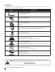
Safety Symbols This page depicts and describes safety symbols that may appear on this product. Read, understand, and follow all instructions on the machine before attempting to assemble and operate. Symbol Description READ THE OPERATOR’S MANUAL(S) Read, understand, and follow all instructions in the manual(s) before attempting to assemble and operate WARNING— ROTATING BLADES Keep hands out of inlet and discharge openings while machine is running.
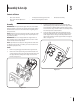
3 Assembly & Set-Up Contents of Carton • One Snow Thrower • Two Replacement Auger Shear Pins • One Snow Thrower Operator’s Manual • One Product Registration Card Assembly NOTE: All references in this manual to the left or right side of the snow thrower is from the operating position only. Exceptions, if any, will be specified. IMPORTANT: This unit is shipped with the engine full of oil. One Chute Assembly 3.
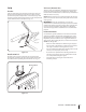
4. Chute Assembly 1. Loosen, but do not remove, the chute crank bracket in order to attached the chute assembly. See Fig. 3-4. Secure flange keeper removed earlier with lock nuts and screws. Tighten down nuts securing the other two flange keepers. See Figure 3-4. Chute Crank Bracket Figure 3-4 Figure 3-3 2. 3. Remove lock nuts and screws securing one of the flange keepers to the chute assembly. Loosen the fasteners of the other two flange keepers. See Figure 3-4. 5.
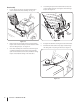
Set-Up Tire Pressure (Pneumatic Tires) Shear Pins A pair of replacement auger shear pins and bow tie cotter pins have been included with your snow thrower. There are holes provided in the plastic dash panel for convenient storage of the shear pins. Push the pins through the holes in the dash panel and secure with the bow-tie cotter pins. See Fig. 3-6. The tires can be over-inflated for shipping purposes. Check the tire pressure before operating the snow thrower.
3. Adding Fuel Warning! Use extreme care when handling gasoline. Gasoline is extremely flammable and the vapors are explosive. Never fuel the machine indoors or while the engine is hot or running. Extinguish cigarettes, cigars, pipes and other sources of ignition. Remove the oil filler cap/dipstick. If the level is low, slowly add oil until oil level registers between high (H) and low (L), Fig. 3-9. Refer to the Engine Maintenance section for correct oil viscosity and engine oil capacity.
Lower Shave Plate Shave Plate Raise Shave Plate Figure 3-10 Auger and Drive Control Cables Warning! Prior to operating your snow thrower, carefully read and follow all instructions below. Perform all adjustments to verify your snow thrower is operating safely and properly. Testing Auger Drive Control 1. When the auger control is released and in the disengaged “up” position, the cable should have very little slack. It should NOT be tight. Refer to Figure 3-11.
Warning! Do not over-tighten the cable. Over- Adjusting Drive and Auger Controls 1. From beneath the handle, pull downward on the appropriate cable and unhook the spring found on the end of the cable from its respective actuator bracket. Refer to Figures 3-11 and 3-12. Rearward most hole of the actuator brackets Figure 3-12 2. Slide the spring up the cable to expose the cable coupler threads and lock nut. Refer to Figure 3-13. Figure 3-13 3.
4 Controls and Features Wheel Drive Control Headlight Speed Selector Lever Two Way Chute Pitch Control™ Fuel Tank Auger Control Fuel Cap Wheel Steering Control Oil Fill Chute Directional Control Chute Assembly Oil Filler Cap/Dipstick Clean-Out Tool Primer Key Fuel Fill Cap Electric Start Button Electric Switch Box Choke Throttle Augers Recoil Starter Handle Skid Shoe Oil Drain Figure 4-1 Snow thrower controls and features are described below and illustrated in Fig. 4-1.
Throttle Control Auger Control The throttle control is located on the rear of the engine. It regulates the speed of the engine and will shut off the engine when moved into the STOP position. Primer Pressing the primer forces fuel directly into the engine’s carburetor to aid in starting a “Cold” engine. NOTE: Do not use the primer bulb to restart a warm engine after a short shutdown. Oil Fill Engine oil level can be checked and oil added through the oil fill.
Two-Way Chute-Pitch Control™ Wheel Steering Controls The two-way chute-pitch control is located on the left side of the dash panel and is used to control the distance of snow discharge from the chute. The left and right wheel steering controls are located on the underside of the handles. Squeeze the right control to turn right; squeeze the left control to turn left. • To change the upper chute angle to control the distance that snow is thrown, pivot the lever forward or backward.
5 Operation Starting The Engine 3. WARNING! Always keep hands and feet clear of moving parts. Do not use a pressurized starting fluid. Vapors are flammable. Plug the extension cord into the electric outlet located on the engine. Plug the other end of extension cord into a three-prong 120-volt, grounded, AC outlet in a wellventilated area. See Fig. 5-2. NOTE: Allow the engine to warm up for a few minutes after starting. The engine will not develop full power until it reaches operating temperatures.
Recoil Starter Caution! Do not pull the starter handle while the To Engage Drive 1. engine running. NOTE: Use slower speeds in higher snow and/or until you are familiar with the snow thrower operation WARNING: To avoid unsupervised engine operation, never leave the engine unattended while running. Turn the engine off after use and remove key 1. Insert key fully into slot, Figure 5-5. Make sure it snaps into place. DO NOT turn key.
Operating Tips Replacing Shear Pins NOTE: Allow the engine to warm up for a few minutes. The engine will not develop full power until it reaches operating temperature. Each of the four auger spiral assemblies are secured to the spiral shaft with a shear pin and cotter pin. If the auger should strike a foreign object or ice jam, the snow thrower is designed so that the pins may shear. If the augers will not turn, check to see if the pins have sheared. See Fig. 5-3.
6 Maintenance & Adjustments Maintenance WARNING! Before servicing, repairing, lubricating, or inspecting, disengage all controls and stop engine. Wait until all moving parts have come to a complete stop. Remove the ignition key, disconnect the spark plug wire and ground it against the engine to prevent unintended starting. Always wear safety glasses during operation or while performing any adjustments or repairs. Engine Refer to the Engine Maintenance section.
Auger Shaft At least once a season, one at a time, remove the shear pins from the auger shaft. Spray lubricant inside the hub of each auger spiral assembly and around the spacers on the auger shaft. See Figure 6-3. Grease fittings can also be found at each end of the auger shaft. Lubricate with a grease gun once a season. See Figure 6-3.
Drive Control 4. If there is no friction wheel clearance when the drive control is disengaged, or the friction wheel does not solidly contact the drive friction plate when the drive control is engaged, re-adjust the lock nut on the lower end of the drive cable following the instructions in the Assembly section. 5. Reassemble the frame cover. Refer to “Auger and Drive Control Cables” of the Assembly & Set-Up Section 3 for instructions to adjust the drive control.
7 Engine Maintenance WARNING! To prevent accidental start-up, shut off the engine and remove the key before performing any type of engine maintenance. Periodic inspection and adjustment of the engine is essential if high level performance is to be maintained. Regular maintenance will also ensure a long service life. The required service intervals and the type of maintenance to be performed are described in the table below. Follow the hourly or calendar intervals, whichever occur first.
Spark Plug WARNING! DO NOT check for spark with spark plug removed. DO NOT crank engine with spark plug removed. 4. Check that the spark plug washer is in good condition and thread the spark plug in by hand to prevent crossthreading. 5. After the spark plug is seated, tighten with a spark plug wrench to compress the washer. NOTE: When installing a new spark plug, tighten 1⁄2-turn after the spark plug seats to compress the washer.
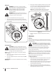
8 Service Belt Replacement Belt Removal Preparation Remove 1. Remove the chute crank assembly bracket by removing the nuts and washers shown in Fig. 8-1. Loosen Nuts & Washers Figure 8-3 Auger Belt Replacement To remove and replace your snow thrower’s auger belt, proceed as follows: Figure 8-1 1. Remove the bow tie clip and flat washer from the ferrule in order to disconnect the auger idler rod from the brake bracket assembly. See Fig. 8-4. 2.
3. Pull the brake bracket assembly towards the cable guide roller and unhook the auger cable “Z” fitting. Refer to Fig. 8-5. 7. Lift the brake bracket assembly out of the pulley groove and slide the pulley assembly off the posts of the auger pulley adapter to remove the old belt. Refer to Fig. 8-7. Adapter Post B C z-fitting A Figure 8-5 4. From both sides of the frame assembly, use a 1/2" wrench to remove the three hex tap screws securing the transmission frame to the auger housing assembly.
NOTE: Make sure to remove the piece of wood blocking the impeller. Check the auger drive belt adjustment. With the auger clutch lever in the disengaged position, the top surface of the new belt should be even with the outside diameter of the pulley. 1. Drain the gasoline from the snow thrower. 2. Tip the snow thrower up and forward, so that it rests on the housing. 3. Remove screws from the frame cover underneath the snow thrower (refer to Fig. 8-9). Remove the right wheel from the axle.
6. Lift the friction wheel assembly out between the axle shaft and the drive shaft assemblies. 7. Remove four screws securing the friction wheel to the hub assembly (refer to Fig. 8-11). Discard old friction wheel. 10. Slide the hex shaft through the right side of the frame toward the left side and through the friction wheel assembly.
Off-Season Storage Long-Term Storage If the snow thrower will not be used for 30 days or longer, the equipment needs to be stored properly. Follow storage instructions below to ensure top performance from the snow thrower for many more years. Engines stored over 30 days need to be drained of fuel to prevent deterioration and gum from forming in fuel system or on essential carburetor parts.
8 Troubleshooting Problem Engine fails to start Cause Remedy 1. Choke not in CHOKE position. 1. Move choke to CHOKE position. 2. Spark plug wire disconnected. 2. Connect wire to spark plug. 3. Fuel tank empty or stale fuel. 3. Fill tank with clean, fresh gasoline. 4. Engine not primed. 4. Prime engine as instructed in “Operating Your Snow Thrower”. 5. Faulty spark plug. 5. Clean, adjust gap, or replace. 6. Safety key not in ignition on engine. 6. Insert key fully into the switch. 7.
9 Replacement Parts Component Part Number and Description 929-0071 Extension Cord, 110V 954-04194A 954-04202 Auger Drive Belt Wheel Drive Belt 918-04178 718-04034 Friction Wheel Assembly Friction Wheel w/Bonded Rubber 725-1629 Lamp 738-04155 714-04040 Shear Pin Bow-tie Cotter Pin 731-07032 Slide Shoe, Deluxe 731-2643 Chute Clean-out Tool 790-00195A Shave Plate, Stainless Steel 731-05632 Key 951-10292 Spark Plug Phone (800) 965-4CUB (4282) to order replacement parts or a complete Parts
Notes 11 31
Section 11— Notes
Section 10 — Notes 33
MTD CONSUMER GROUP INC (MTD), the California Air Resources Board (CARB) and the United States Environment Protection Agency (U. S. EPA) Emission Control System Warranty Statement (Owner’s Defect Warranty Rights and Obligations) EMISSION CONTROL SYSTEM COVERAGE IS APPLICABLE TO CERTIFIED ENGINES PURCHASED IN CALIFORNIA IN 2005 AND THEREAFTER, WHICH ARE USED IN CALIFORNIA, AND TO CERTIFIED MODEL YEAR 2005 AND LATER ENGINES WHICH ARE PURCHASED AND USED ELSEWHERE IN THE UNITED STATES.
(4) Repair or replacement of any warranted part under the warranty provisions of this article must be performed at no charge to the owner at a warranty station. (5) Notwithstanding the provisions of Subsection (4) above, warranty services or repairs must be provided at all MTD distribution centers that are franchised to service the subject engines.
CUB CADET LLC MANUFACTURER’S LIMITED WARRANTY FOR snow throwers The limited warranty set forth below is given by Cub Cadet LLC with respect to new merchandise purchased and used in the United States, its possessions and territories, and by MTD Products Limited with respect to new merchandise purchased and used in Canada and/or its territories and possessions. b.