Safe Operation Practices • Set-Up • Operation • Maintenance • Service • Troubleshooting • Warranty Operator’s Manual Two Stage Snow Thrower — Model 945 SWE WARNING READ AND FOLLOW ALL SAFETY RULES AND INSTRUCTIONS IN THIS MANUAL BEFORE ATTEMPTING TO OPERATE THIS MACHINE. FAILURE TO COMPLY WITH THESE INSTRUCTIONS MAY RESULT IN PERSONAL INJURY. CUB CADET LLC, P.O. BOX 361131 CLEVELAND, OHIO 44136-0019 Printed In USA FORM NO.
1 To The Owner Thank You Thank you for purchasing a Snow Thrower manufactured by Cub Cadet LLC. It was carefully engineered to provide excellent performance when properly operated and maintained. Please read this entire manual prior to operating the equipment. It instructs you how to safely and easily set up, operate and maintain your machine. Please be sure that you, and any other persons who will operate the machine, carefully follow the recommended safety practices at all times.
Important Safe Operation Practices 2 WARNING! This symbol points out important safety instructions which, if not followed, could endanger the personal safety and/or property of yourself and others. Read and follow all instructions in this manual before attempting to operate this machine. Failure to comply with these instructions may result in personal injury. When you see this symbol.
Safe Handling of Gasoline 5. To avoid personal injury or property damage use extreme care in handling gasoline. Gasoline is extremely flammable and the vapors are explosive. Serious personal injury can occur when gasoline is spilled on yourself or your clothes which can ignite. Wash your skin and change clothes immediately. Never run an engine indoors or in a poorly ventilated area. Engine exhaust contains carbon monoxide, an odorless and deadly gas. 6.
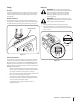
Clearing a Clogged Discharge Chute Hand contact with the rotating impeller inside the discharge chute is the most common cause of injury associated with snow throwers. Never use your hand to clean out the discharge chute. To clear the chute: 1. SHUT THE ENGINE OFF! 2. Wait 10 seconds to be sure the impeller blades have stopped rotating. 3. Always use a clean-out tool, not your hands. Maintenance & Storage 1. Never tamper with safety devices. Check their proper operation regularly.
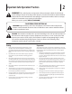
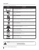
Safety Symbols This page depicts and describes safety symbols that may appear on this product. Read, understand, and follow all instructions on the machine before attempting to assemble and operate. Symbol Description READ THE OPERATOR’S MANUAL(S) Read, understand, and follow all instructions in the manual(s) before attempting to assemble and operate WARNING— ROTATING BLADES Keep hands out of inlet and discharge openings while machine is running.
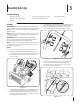
3 Assembly & Set-Up Contents of Carton • One Snow Thrower • Two Replacement Auger Shear Pins • One Snow Thrower Operator’s Manual • One Product Registration Card Assembly 4. IMPORTANT: Two replacement auger shear pins are included with this manual (or stowed in the plastic handle panel). Refer to the Maintenance section for more information regarding shear pin replacement. • One Chute Assembly Secure the upper handle and lower handle with the two wing nuts and carriage bolts removed earlier.
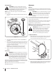
NOTE: If the connector is not properly assembled, the shift rod will pivot and you will not be able to change speeds or direction. If the full range of speeds (forward and reverse) can not be achieved, refer to the “Maintenance and Adjustments” section. Place chute assembly onto chute base as shown in Fig. 3-5. Make sure that the chute notches engage with the spiral end of chute directional control, and the two flange keepers are beneath the flange on the chute base.
Set-Up Adding Fuel Warning! Use extreme care when handling gasoline. Gasoline is extremely flammable and the vapors are explosive. Never fuel the machine indoors or while the engine is hot or running. Extinguish cigarettes, cigars, pipes and other sources of ignition. Shear Pins A pair of replacement auger shear pins and bow tie cotter pins have been included with your snow thrower. Store the pins in a convenient place for use if an original equipment shear pin should break.
Adjustments Checking Oil Level CAUTION: The engine is shipped with oil in the engine. You must, however, check the oil level prior to operating the snow thrower. Running the engine with insufficient oil can cause serious engine damage and void the engine warranty. Skid Shoes The snow thrower skid shoes are adjusted upward at the factory for shipping purposes. Adjust them downward prior to operating the snow thrower.
3. Make certain the entire bottom surface of skid shoes are against the ground to avoid uneven wear on the skid shoes; then tighten nuts and bolts securely. Testing Drive Control & Shift Lever 1. With the engine turned off, move the shift lever into sixth (6) position. Refer to Fig. 3-11. 2. With the wheel drive control released, push the snow thrower forward, then pull it back. The machine should move freely. 3.
2. Slide the spring up the cable to expose the cable coupler threads and lock nut. Refer to Fig. 3-13. Figure 3-13 3. Adjust the lock nut as follows: If adjusting the drive cable, thread the lock nut outward (down the coupler) to lengthen the cable and allow the unit to move freely when the control is released. Thread the lock nut inward (up the coupler) to shorten the cable to reduce slippage and prevent the machine from being easily moved with the drive control engaged.
4 Controls and Features Drive Control Speed Selector Shift Lever Two-way Chute Control™ Headlight Auger Control Chute Assembly Wheel Steering Control Clean-out Tool Chute Directional Control Oil Filler Cap/Dipstick Primer Gas Cap Key Electric Start Button Electric Starter Outlet Augers Auger Housing Recoil Starter Handle Choke Throttle Skid Shoes Oil Drain Figure 4-1 Snow thrower controls and features are described below and illustrated in Fig. 4-1.
Throttle Control Auger Control The throttle control is located on the rear of the engine. It regulates the speed of the engine and will shut off the engine when moved into the STOP position. Primer Bulb Pressing the primer bulb forces fuel directly into the engine’s carburetor to aid in starting a “Cold” engine. NOTE: Do not use the primer bulb to restart a warm engine after a short shutdown. Oil Filler Cap / Dipstick Engine oil level can be checked and oil added through the oil fill.
Two-Way Chute Control™ Wheel Steering Controls The two-way chute control is located on the left side of the dash panel and is used to control the distance of snow discharge from the chute. The left and right wheel steering controls are located on the underside of the handles. Squeeze the right control to turn right; squeeze the left control to turn left. • To change the upper chute angle to control the distance that snow is thrown, pivot the lever forward or backward.
5 Operation Starting The Engine Recoil Starter 1. 1. Attach spark plug wire to spark plug. Make certain the metal loop on the end of the spark plug wire (inside the rubber boot) is fastened securely over the metal tip on the spark plug. 2. Make certain both the auger control and drive control are in the disengaged (released) position. 3. Move throttle control up to FAST position. Insert key into the ignition switch. Make sure it snaps into place. Do not attempt to turn the key.
To Engage Drive Operating Tips 1. NOTE: Allow the engine to warm up for a few minutes. The engine will not develop full power until it reaches operating temperature. With the throttle control in the Fast (rabbit) position, move shift lever into one of the six forward (F) positions or two reverse (R) positions. Select a speed appropriate for the snow conditions and a pace you’re comfortable with. WARNING: The temperature of the muffler and the surrounding areas may exceed 150° F. Avoid these areas.
6 Maintenance & Adjustments WARNING! Before performing any type of maintenance/service, disengage all controls and stop the engine. Wait until all moving parts have come to a complete stop. Remove the key to prevent unintended starting. Always wear safety glasses during operation or while performing any adjustments or repairs. ENGINE MAINTENANCE Changing Engine Oil NOTE: Change the engine oil after the first 5 hours of operation and once a season or every 50 hours thereafter. 1.
Checking Spark Plug WARNING! DO NOT check for spark with spark plug removed. DO NOT crank engine with spark plug removed. WARNING! If the engine has been running, the muffler will be very hot. Be careful not to touch the muffler. NOTE: Check the spark plug once a season or every 25 hours of operation. Change the spark plug once a season or every 100 hours. 4. Check that the spark plug washer is in good condition and thread the spark plug in by hand to prevent crossthreading. 5.
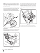
Auger Shaft Shave Plate At least once a season, one at a time, remove all of the shear pins from the auger shaft. Spray lubricant inside the hub of each auger spiral assembly and around the spacers on the auger shaft. 1. Remove the hex nuts and carriage bolts that secure the shave plate to the bottom of the housing. See Fig. 6-7. 2. Remove the rear most hex nut and carriage bolt securing the back of each skid shoe to the sides of the housing. Loosen the four remaining hex nuts securing the skid shoes.
Chute Control Chute Bracket The distance snow is thrown can be adjusted by adjusting the angle of the chute assembly. Refer to the Operation section for instructions. If the spiral at the bottom of the chute directional control is not fully engaging with the chute assembly, the chute bracket can be adjusted. To do so: The remote chute control cables have been pre-adjusted at the factory.
7 Service Belt Replacement Belt Removal Preparation Remove 1. Remove the cotter pin which secures the upper chute crank to the lower chute crank. Refer to Figure 7-1. Loosen Figure 7-3 Auger Belt Replacement To remove and replace your snow thrower’s auger belt, proceed as follows: Figure 7-1 2. Remove the plastic belt cover on the front of the engine by removing the three self-tapping screws. See Fig. 7-2. Figure 7-2 3. Loosen the bolt shown in Fig.
3. Pull the brake bracket assembly towards the cable guide roller and unhook the auger cable “Z” fitting. Refer to Fig. 7-5. 7. Lift the brake bracket assembly out of the pulley groove and slide the pulley assembly off the posts of the auger pulley adapter to remove the old belt. Refer to Fig. 7-7. Adapter Post B C A Figure 7-5 4. From both sides of the frame assembly, use a 1/2" wrench to remove the three hex tap screws securing the transmission frame to the auger housing assembly. Refer to Fig. 7-1.
NOTE: Make sure to remove the piece of wood blocking the impeller. Check the auger drive belt adjustment. With the auger clutch lever in the disengaged position, the top surface of the new belt should be even with the outside diameter of the pulley. To adjust, disconnect ferrule from brake bracket assembly. Thread ferrule in (towards idler) to increase tension on belt, or out to decrease belt tension. 1. Drain the gasoline from the snow thrower, or place a piece of plastic under the gas cap. 2.
6. Lift the friction wheel assembly out between the axle shaft and the drive shaft assemblies. 7. Remove four screws securing the friction wheel to the hub assembly (refer to Fig. 7-11). Discard old friction wheel. 10. Slide the hex shaft through the right side of the frame toward the left side and through the friction wheel assembly.
Off-Season Storage Long-Term Storage If the snow thrower will not be used for 30 days or longer, the equipment needs to be stored properly. Follow storage instructions below to ensure top performance from the snow thrower for many more years. Engines stored over 30 days need to be drained of fuel to prevent deterioration and gum from forming in fuel system or on essential carburetor parts.
8 Troubleshooting Problem Engine fails to start Cause Remedy 1. Choke not in CHOKE position. 1. Move choke to CHOKE position. 2. Spark plug wire disconnected. 2. Connect wire to spark plug. 3. Fuel tank empty or stale fuel. 3. Fill tank with clean, fresh gasoline. 4. Engine not primed. 4. Prime engine as instructed in “Operating Your Snow Thrower”. 5. Faulty spark plug. 5. Clean, adjust gap, or replace. 6. Safety key not in ignition on engine. 6. Insert key fully into the switch. 7.
9 Replacement Parts Component Part Number and Description 929-0071 Extension Cord, 110V 954-04194A 954-04202 Auger Drive Belt Wheel Drive Belt 918-04178 718-04034 Friction Wheel Assembly Friction Wheel w/Bonded Rubber 725-1658 Lamp 738-04155 714-04040 Shear Pin Bow-tie Cotter Pin 731-07032 Slide Shoe, Deluxe 731-2643 Chute Clean-out Tool 790-00195A Shave Plate, Stainless Steel 731-05632 Key 951-10292 Spark Plug Phone (800) 965-4CUB (4282) to order replacement parts or a complete Parts
Notes 10 29
MTD CONSUMER GROUP INC (MTD), the California Air Resources Board (CARB) and the United States Environment Protection Agency (U. S. EPA) Emission Control System Warranty Statement (Owner’s Defect Warranty Rights and Obligations) EMISSION CONTROL SYSTEM COVERAGE IS APPLICABLE TO CERTIFIED ENGINES PURCHASED IN CALIFORNIA IN 2005 AND THEREAFTER, WHICH ARE USED IN CALIFORNIA, AND TO CERTIFIED MODEL YEAR 2005 AND LATER ENGINES WHICH ARE PURCHASED AND USED ELSEWHERE IN THE UNITED STATES.
(4) Repair or replacement of any warranted part under the warranty provisions of this article must be performed at no charge to the owner at a warranty station. (5) Notwithstanding the provisions of Subsection (4) above, warranty services or repairs must be provided at all MTD distribution centers that are franchised to service the subject engines.
CUB CADET LLC MANUFACTURER’S LIMITED WARRANTY FOR snow throwers The limited warranty set forth below is given by Cub Cadet LLC with respect to new merchandise purchased and used in the United States, its possessions and territories, and by MTD Products Limited with respect to new merchandise purchased and used in Canada and/or its territories and possessions. b.