Operator's M nual 21" Self-Propelled Mower Model 997A71X IMPORTANT: Read safety rules and instructions carefully Warning: This unit is equipped with an internal combustion engine and should not be used on or near any unimproved forest-covered, brush-covered or grass-covered land unless the engine's exhaust system is equipped with a spark arrester meeting applicable local or state laws (if any). if a spark arrester is used, it should be maintained in effective working order by the operator.
TABLEOFCONTENTS Content Important Safe Operation Practices Slope Guage Assembling Your Lawn Mower Know Your Lawn Mower Operating Your Lawn Mower 10 Making Adjustments Page 3 6 7 9 Content Maintaining Your Lawn Mower Servicing Your Lawn Mower Off-Season Storage 16 Troubleshooting Illustrated Parts List Warranty 11 Page 13 14 17 20 36 FINDINGMODELNUMBER This Operator's Manual is an important part of your new lawn mower. It will help you assemble, prepare and maintain the unit for best performance.
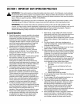
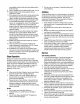
SECTION 1: IMPORTANT SAFEOPERATION PRACTICES ,_ WARNING: This and/or symbol property points out safety instructions which, notinstructions followed, could the personal safety of important yourself and others. Read and followif all in thisendanger manual before attempting to operate this machine. Failure to comply with these instructions may result in personal injury. When you see this symbol--HEED ITS WARNING.
immediately andthebladewillstoprotatingwithin 3. Do not mow on wet grass. Unstable footing could threeseconds. cause slipping. 9. Mowindaylightorgoodartificiallight;walk,notrun. 10.Stopthebladewhencrossinggraveldrives, Children walkways or roads. accidents can occur if the operator is not alert to 11. Iftheequipment shouldstarttovibrateabnormally, Tragic the presence of children. Children are often attracted to stoptheengineandcheckimmediately forthe the mower and the mowing activity. They do not cause.
10.Neveroverfillfueltank.Filltankto nomorethan½ inchbelowbottomoffillernecktoprovidespacefor fuelexpansion. 11.Replacegasolinecapandtightensecurely. 12. Ifgasolineisspilled,wipeitofftheengineand equipment. Moveunittoanotherarea.Wait5 minutesbeforestartingtheengine. 13.Neverstorethemachineorfuelcontainerinside wherethereisanopenflame,sparkorpilotlightas onawaterheater,spaceheater,furnace,clothes dryerorothergasappliances. 14.Toreducefirehazard,keepmowerfreeofgrass, leaves,orotherdebrisbuild-up.
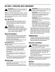
SIGHT AND HOLD THIS LEVEL WITH A VERTICAL TREE C A POWER POLE A CORNER OF A BUILDING o "" ~.... i ,q i OR A FENCE POST iq O c O t_ co 03 ¢0 O. O CO E t.O l O 0_ o. I,U _o I,M "_ .=.° 5 WARNING co O_1 03 CO . _ Do not mow on inclines with a slope in excess of 15 degrees (a rise of approximately 2-1/2 feet every 10 feet). A riding mower could CO O o.-- ._ _ =_ _ o and you could slip, resulting in serious injury.
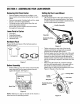
SECTION3: ASSEMBLING YOURLAWNMOWER RemovingUnitFromCarton Remove staples, break glue on top flaps, or cut tape at carton end and peel along top flap to open carton. Remove loose parts, if included with unit (i.e., grass bag etc.), and save it appropriately. Cut along corners, lay the carton down flat, and remove all packing material.
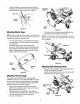
Fastenthecabletothelowerhandlewiththetwo cabletiesfoundonthelowerhandle.Pullthecable tiestightandtrimofftheexcess.SeeFigure5. Grass Bag Cable Tie. Handle Nuts Figure5 Figure7 AttachingStarterRope Lift chutedooron the grass bag adapter and slide grass bag onto the adapter. See Figure8. NOTE: Make certain the drive cable is routed around the outside and above the lower handle so it does not interfere with attaching the grass bag.
SECTION4: KNOWYOURLAWNMOWER Read this operator's manual and safety rules before operating your lawn mower. Compare the illustration in Figure 10 with your lawn mower to familiarize yourself with the location of various controls and adjustments. Save this manual for future reference. _ WARNING: The operation of any lawn mower can result in foreign objects being thrown into the eyes, which can damage your eyes severely.
SECTION5: OPERATING YOURLAWNMOWER ,_ il_ WARNING: understand, and follow all instructions andRead, warnings on the machine and WARNING: Be sure no one other than the operator is standing near the lawn mower while starting engine or operating mower. in this manual before operating. NOTE: For shipping purposes your mower is set with the wheels in a low cutting height position. For best results, raise the cutting position until it is determined which height is best for your lawn.
thrownbythemowerinanydirectionandcauseserious personalinjurytotheoperatorandothers. _ WARNING: Attach grass catcher following instructions on page 8 of this manual. Grass clippings will automatically collect in the bag as you run the mower. Operate the mower till the grass bag is full. Stop engine completely by releasing the blade control handle. Make sure that the unit has come to If the mower strikes a foreign object, stop the engine.
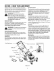
The front wheel cutting height is determined by selecting one of six positions on each caster assembly. To adjust front cutting height, proceed as follows: Bottom View ® Remove the wing nut from the axle bolt. See Figure 13. Slide the axle bolt and spring washer from the assembly and select a cutting height. With the spring washer on the axle bolt, reinsert hardware in the square hole desired through the wheel assembly and secure with the wing nut previously removed.
SECTION7: MAINTAINING YOURLAWNMOWER _lb WARNING: Inspect muffler periodically, and replace if necessary. Damaged mufflers or spark arresters can create a fire hazard. Make sure to avoid muffler Always stop the engine and disconnect the spark plug wire before performing any maintenance work or adjustments on your lawn mower. and surrounding areas while the mower engine is hot because temperature of these areas of the engine may exceed 150° F.
SECTION8: SERVICING THEMOWER _1= WARNING: Place the blade on the adapter. Be certain the blade is aligned and seated on the blade adapter flanges. Place blade bell support on blade. Make sure the notches on the blade bell support are aligned with small holes in the blade. Always stop the engine and disconnect the spark plug wire before performing any maintenance work or adjustments on your lawn mower. BladeCare _ WARNING: Replace hex bolt and tighten hex bolt to torque: 450 in. lbs. min., 600 in.
Remove the hex bolt from the rear of unit holding the transmission to the mower housing. See Figure 19. Pivot the control arm down away from the pulley and belt. Lift off the lower pulley assembly and remove the old belt from around the crankshaft. Place the new belt over the transmission pulley. Start the belt in the pulley groove and rotate the pulley until the belt is seated in transmission pulley. Place the belt between the idler pulley and the belt keeper bracket.
Attach the new flap and new rod to deck, bending the ends of the new rod over to secure to deck. Six-Speed ReplacingBatteryPack (Model E977 only) Remove the battery pack from the handle panel for replacement only. Do not separate the batteries for any reason. Dispose of batteries properly. When replacing battery pack in handle panel, battery pack must be positioned with the positive terminal to the right side and the negative terminal to the left side of the panel.
SECTION 10: TROUBLESHOOTING Problem Cause Remedy Engine fails to start 1. 2. 3. 4. 5. 6. Blade control handle disengaged. Spark plug wire disconnected. Fuel tank empty or stale fuel. Blocked fuel line. Faulty spark plug. Engine flooded 1. 2. 3. 4. 5. 6. Engage blade control handle. Connect wire to spark plug. Fill tank with clean, fresh gasoline. Clean fuelline. Clean, adjust gap, or replace. Wait a few minutes to restart, do not prime. Engine runs erratic 1. 2. Spark plug wire loose.
YOURNOTES Date Comments I 18
Safety& DecorativeLabels Some of the labels found on your mower are representeted here with the corresponding part numbers. Please use these part numbers when ordering replacement labels.
SECTION 11: PARTSLISTFORMODEL997 20 100 48 27 29 59 \ _3 99 78 8 IMPORTANT: For a proper working machine, use Factory Approved Parts. V-BELTS are specially designed to engage and disengage safely. A substitute (non OEM) V-Belt can be dangerous by not disengaging completely.
Model997 ReL No. 1, 547-00408 Control Handle 2, 3, 4, 131-0904A 16864 731-0620 5, 6, 7, 713-0397 132-0627 731-0924 Upper Control Handle 6 Spd.
Model997 15 ! / \ \ 24. \ 8 "1o \ 12 31 6, I 62 22
Model997 Ref. No. Part No. Ref. No. Part Description Part No. Part Description 1. 2. 720-0223 732-0803A Grip 32. 736-3084 Flat Washer .510 ID x 1.120 OD Spring Lever 33. 712-0896 Hex Jam Nut 1/4-28 3. 738-0529 Shoulder Nut .825 x.165 Lg. 34. 782-7598 Belt Keeper 4. 5. 710-0751 736-0270 Cap Screw 1/4-20 x .620 Bell Washer .285 ID x .75 OD 35. 741-0600 Bearing 36. 732-6849A Extension Spring 6. 7. 748-0318 736-0369 Wheel Rachet Flat Washer ,508 ID x 1.00D 37. 38.
EngineManualfor KawasakiEngine SAFETYAWARENESS ,_ WARNING: Whenever you see the symbols shown on the left, heed their instructions!Always follow safe operating and maintenance practices. FORWARD We wish to thank you for purchasing this Kawasaki engine. Please read this Owner's manual carefully before starting your new engine so that you will be thoroughly familiar with the proper operation of your engine's control, its features, capabilities and limitations.
READTHISFIRST _lb WARNING: Never allow children to operate the engine or equipment. Keep people and pets out of area where you are using the engine or equipment. Never wear loose, torn, or bulky clothing. It may catch on moving parts or controls, leading to the risk of accident. Never consume alcohol or drug before or while operating this engine. Do not run the engine in a closed area. Exhaust gas contains carbon monoxide, an odorless and deadly poison.
gasses are led to a breather chamber through the crankcase and from there to the air cleaner. necessary to ensure compliance with the applicable standards. Engine EmissionsCompliancePeriod California As the owner of the engine, you have the responsibility to make sure that the recommended maintenance is Model Year - 2006 and later Vertical Crankshaft carried out according to the instructions in this Owner's Manual at your own expense.
GeneralInformation Locationof Safety RelatedLabels Figure 3 A. Fuel Tank Cap Figure 1 a. b. B. Fuel Tank (capacity 2.0L [0.528US gal.]) C. Fuel Tube Warning Engine Maintenance D. Carburetor E. Priming Pump F. Air Cleaner AWARNING G. Recoil starter _*FOR rEADOWNER'SMANUAL SAFE OPERATION •GASOLINE S FLAMMABLE KEEPAWAY FROMFLAME OR SPARKS _IIk.EXHAUSTGARIS PO SOHOUS O0 AN NO-RUNENBNE ENCLOSED AREA N ;_,TO ,_ RUFFLER • UI I. Oil Drain Plugs (engine oil capacity 0.65L [0.69US gal.
FuelAndOilRecommendations -2C C -10°C O°C 10°C 20°C 30°C 40°C Fuel Use only gasoline. clean, fresh, unleaded regular grade OctaneRating The octane rating of a gasoline is a measure of its resistance to "knocking".Use a minimum of 87 octane of the antiknock index is recommended. The antiknock index is posted on service station pumps in the U.S.A. Figure 5 NOTE: If "knocking or pinging" occurs, use a different brand of gasoline orhigher octane rating.
CAUTION:The engine oil. engine is shipped without DO NOT let the recoil starter grip snap back itself. This may cause damage to the recoil starter assembly. Hold the brake control lever (A) on the equipment against the handle (B) on the equipment. Pull the recoil starter grip ((3) slowly until you feel compression, then pull fast and steady. Figure 7 Starting BandPad System Upon releasing the brake control lever on the equipment, the cutting blade and the engine will stop automatically. Figure 9 A.
B. Handle Adjustment EngineSpeedAdjustment NOTE: DO not tamper with the governor setting or the carburetor setting to increase the engine speed. Each carburetor is adjusted at the factory with either a cap or stop plate installed on the mixture screw. Any adjustments must be performed an authorized Kawasaki dealer.
Putthemowerbacktoitsoperating position(onall fourwheels). RefillingFreshOil Remove dipstick and refill with new oil (See FUEL AND OIL RECOMMENDATIONS chapter). Dipstick_ NOTE: If you followed the second method of draining oil, the dipstick is already removed from the engine. Check the oil level (See PREPARATION chapter), and secure dipstick to the filler plug. _lb WARNING: Engine oil is toxic substance. Dispose of used oil properly.
A. Fasteners A. Slit in the air cleaner body B. Recoil Starter B. Projection on the air cleaner case C. Fasteners C. Air Cleaner Case D. Air Cleaner body E. Latches CAUTION: After servicing the air cleaner, be sure all the removed parts are reinstalled properly in place. Failure to secure fastening of the air cleaner case with the air cleaner body may cause dirt or other foreign materials to enter the engine, while it is running, through the air cleaner, resulting in engine troubles or failures.
Storage Engine to be stored over 30 days should be completely drained of fuel (gasoline) to prevent gum deposits forming on essential carburetor parts and fuel system. _b WARNING: Gasoline is extremely flammable and can be explosive under certain conditions. Drain gasoline before storing the equipment for extended periods. Drain gasoline in a well-ventilated area away from any source of flame or sparks, including any appliances with a pilot light.
Troubleshooting Guide Symptom Engine won't start output is low Probable Insufficient compression 1. Cause 2. 3. 4. Faulty piston, cylinder, piston ring, and head gasket Faulty valves Loose spark plug Loose cylinder head bolts 1. 2. 3. 4. No fuel in fuel tank Blocked rue tube Blocked air vent in fuel tank cap Faulty carburetor 1. Over-rich fuel/air mixture 2. 3. 4. 5. Clogged air cleaner Faulty carburetor Incorrect grade/type of fuel Water in fuel No spark or weak spark 1. 2. 3.
Kawasaki Emission Limited Control Warranty: Systems: California Small And Off-Road Federal Engines The California Air Resources Board, the Environmental Protection Agency (EPA), and Kawasaki Motors Corp., U.S.A. (hereinafter "Kawasaki") are pleased to explain the Emission Control Systems Warranty on your Kawasaki small off-road engine. In California and other states, new small off-road engines must be designed, built and equipped to meet stringent anti-smog standards.
MANUFACTURER'S LIMITED WARRANTY FOR: ® The limited warranty set forth below is given by Cub Cadet LLC with respect to new merchandise purchased and used in the United States, its possessions and territories. "Cub Cadet" warrants this product against defects in material and workmanship for a period of two (2) years commencing on the date of original purchase and will, at its option, repair or replace, free of charge, any part found to be defective in materials or workmanship.