Professional Shop Manual Model 188 and CC 500 BAT Cordless Mower NOTE: These materials are for use by trained technicians who are experienced in the service and repair of outdoor power equipment of the kind described in this publication, and are not intended for use by untrained or inexperienced individuals. These materials are intended to provide supplemental information to assist the trained technician.
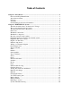
Table of Contents Chapter 1: Introduction ......................................................................................................1 Professional Shop Manual Intent ..................................................................................... 1 About the text format .......................................................................................................1 Fasteners .............................................................................................................
Chapter 3: Repair Procedures ..........................................................................................21 General safety warning ..................................................................................................21 Blades .............................................................................................................................21 Switch box assembly .....................................................................................................
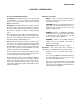
INTRODUCTION CHAPTER 1: INTRODUCTION About the text format Professional Shop Manual Intent NOTE: is used to point-out information that is relevant to the procedure, but does not fit as a step in the procedure. This Manual is intended to provide service dealers with an introduction to the electrical and mechanical aspects of the new cordless electric mower for both MTD and Cub Cadet. CAUTION: Indicates a potentially hazardous situation that, if not avoided, may result in minor or moderate injury.
INTRODUCTION Fasteners Understanding model and serial numbers • The model number is 18A-188-710. The break down of what the number mean is as follows: • • Most of the fasteners used on the vehicle are sized in fractional inches. Some are metric. For this reason, wrench sizes are frequently identified in the text, and measurements are given in U.S. and metric scales.
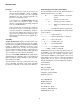
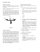
ELECTRICAL SYSTEM CHAPTER 2: ELECTRICAL SYSTEM ELECTRICAL THEORY Ohm’s law In order to diagnosis any electrical system there are few things the technician must know: Ohm’s law state that voltage is the product of resistance times current. It is written as V=IxR. An example of how ohm’s law works goes like this: It takes 1 volt to push 1 amp through a resistance of 1 ohm (1=1x1). Ohm’s law can be drawn in a triangle.
ELECTRICAL SYSTEM Kirchhoff’s current law How the system is wired together Kirchhoff’s current law deals with nodes. Nodes are the junction of two or more wires or the junction of a wire to a component. All circuits have some basic rules that must be followed: 1. All circuits must have at least one voltage source. It is could be a battery, an altenator or both. 2. All circuits must have a load. To make a circuit with out a load is the same as shorting out the power source.
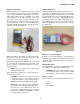
ELECTRICAL SYSTEM Digital volt ohm meter Inductive amp meter Digital volt ohm meters or DVOMs are the most useful tool to troubleshoot any electrical system. Depending on the model of DVOM used, DVOMs can measure Volts, Amps, Ohms and more. DVOMs are a must when working on circuits with solid state components (microchips). They have very high impedance, that means they have very high resistance and pull very little current from the circuit.
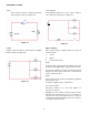
ELECTRICAL SYSTEM Series/parallel Series • Series/parallel circuits have some sections wired in series and some in parallel. See Figure 2.7. Series circuits are wired so that the current has only one path to follow. See Figure 2.5. Switch Bulb Battery Figure 2.5 Figure 2.7 Parallel Types of failures Parallel circuits are wired so that current has multiple paths to follow. See Figure 2.6. There are three types of failures that can occur in an electrical circuit: 1. Shorts 2. Opens 3.
ELECTRICAL SYSTEM Switches Testing a diode: To test a switch: 1. Isolate the diode in the circuit. 1. Remove the switch from the circuit. 2. 2. Set the DVOM to the ohms scale (Ω). Set the DVOM See Figure 2.9. 3. With the switch in the off position touch one probe to one of the tabs and the other probe to the other tab. 4. For a NC switch there should be zero resistance. For a NO switch the meter should show an open circuit. 5. With the probes still attached, turn the switch on.
ELECTRICAL SYSTEM 5. There should be continuity. See Figure 2.10. Fuses Fuses can be visually inspected to indicate they are bad/blown (a dark spot or the element inside will be in two pieces). Some times a fuse can be bad and not show signs of this visually. Any time a fuse is removed from a circuit, it should be tested for continuity with an ohm meter before reinstalling. See Figure 2.12. Continuity Silver band (-) (+) Figure 2.10 6. Switch the leads. 7. The meter should See Figure 2.11.
ELECTRICAL SYSTEM After assuring the breaker is set and the safety key is in place, remove the motor cover by following the steps outlined in Chapter 3: Repair Procedures, and check the fuse. If the fuse is ok, then troubleshoot the electrical system of this mower by looking at three components: Initial trouble shooting The first step in trouble shooting this mower is to make sure the circuit breaker is set. To do this, first make sure the mower is cold (has not been operated for at least five minutes).
ELECTRICAL SYSTEM 5. Checking the motor To test the motor: 1. Remove the motor cover by following the steps described in Chapter 3: Repair Procedures. 2. Disconnect the motor from the harness. See Figure 2.15. The reading on the meter should be within .1 volts of the battery voltage. If it is, the switch box is working properly and by process of elimination, the motor is the problem. NOTE: The motor is not serviceable. NOTE: If the reading is between .
ELECTRICAL SYSTEM 1c. Carefully separate the halves of the switch box. Remove the side that fits against the handle bar.. See Figure 2.20. Testing the switch box and harness IMPORTANT: If the mower is within the warranty period, Do Not open the switch box. Replace the entire switch box for warranty. Outside of warranty, the switch box is serviceable. 1. To test the components inside the switch box, remove and open the switch box by: 1a. Remove the two mounting screws with a T25 torx driver. See Figure 2.
ELECTRICAL SYSTEM 2c. Circuit 1 is a normally closed circuit. That means there should be continuity through that circuit when the switch is at rest. 2d. To test that part of the switch, attach a DVOM to the circuit. Set the meter to the Ohms or “Ω” scale. The meter should read zero ohms. See Figure 2.22. 2f. Circuit 2 is a normally open circuit. That means there should not be continuity through that circuit when the switch is at rest. 2g. To test that part of the switch, attach a DVOM to the circuit.
ELECTRICAL SYSTEM 3. 4. Test the circuit breaker. Test the diode. NOTE: There is a diode between the charger jack and the circuit breaker. It has two jobs. First it protects the batteries from a short in the charger jack, like a child inserting something into the charger jack. Secondly it helps to protect the charger from a back-feed when the mower is operated with the charger plugged in. See Figure 2.28. NOTE: Make sure the circuit breaker is cool and pressed in before testing it. 3a.
ELECTRICAL SYSTEM 4d. 4b. Remove the fuse. See Figure 2.29. Set the DVOM to the diode test scale. See Figure 2.31. Fuse Diode test scale Figure 2.29 Figure 2.31 4c. Disconnect the circuit breaker. See Figure 2.30. 4e. Insert the positive probe of the DVOM into the port of the charger jack that has the green wire. Unplug the circuit breaker 4f. Insert the negative probe into the connector of the wire disconnected from the circuit breaker. See Figure 2.32. Negative probe Figure 2.
ELECTRICAL SYSTEM 4g. The DVOM should read less than 1 Ohm. Batteries and charger 4h. Reverse the leads. See Figure 2.33. Batteries Before an electrical system can be diagnosed, the battery must be fully charged and in good working order. Positive probe Charging the battery NOTE: Batteries on most modern outdoor power equipment are 12 volts. This mower uses a bank of four, sealed 12 volt lead-acid batteries. The four act as one and should be looked at and treated as one big battery.
ELECTRICAL SYSTEM 3. Interpreting the results Attach a digital amp clamp to either one of the motor leads (the current will be positive or negative depending on which LED is used). Table 1: Voltage Current >47.0 < 9.5 Normal readings >47.0 >9.5 High load on motor, a short in the harness or motor worn out. Check for grass build up underneath the deck. 44.0-47.0 < 9.5 Battery pack low or one battery going bad, charge the battery pack and retest. < 44.0 < 9.5 Battery pack is bad. < 44.
ELECTRICAL SYSTEM Battery charger Battery indicator The batteries in the battery pack are wired in series resulting in a 48 volt system. The battery charger for this mower has an output of 54.5 volts so that the whole battery pack is charged at one time. This mower is equipped with a battery level indicator. The indicator has five LEDs, the number of LEDs that are lit is an indication of the voltage level of the battery. It will only light up when the mower is in operation.
ELECTRICAL SYSTEM 4. Attach an alligator clip on to a piece of wire, at least 12” in length. 5. Solder the piece of wire onto one of the other two pins on the variable resistor. See Figure 2.38. Testing the battery indicator NOTE: The battery pack should be fully charged to test the battery indicator. Alligator clip 1. Disconnect the charger from the mower. 2. Remove the motor cover by following the steps described in Chapter 3: Repair Procedures. 3. Unplug the wires from the battery indicator.
ELECTRICAL SYSTEM 8. Attach the positive lead of a DVOM to the positive (smaller) tab of the indicator. See Figure 2.40. 12. Table 2: Positive lead of DVOM Tester leads Figure 2.40 9. LED operation LED 1 LED 2 LED 3 LED 4 LED 5 Voltage green green green green red 52 - 47.9 ON ON ON ON OFF 47.946.7 OFF ON ON ON OFF 46.745.2 OFF OFF ON ON OFF 45.240.4 OFF OFF OFF ON OFF 40.
ELECTRICAL SYSTEM System schematic drawing Circuit Breaker 20
REPAIR PROCEDURES CHAPTER 3: REPAIR PROCEDURES To replace the blade: General safety warning WARNING: When removing the cutting blade for sharpening or replacement, protect your hands with a pair of heavy gloves or use a heavy rag to hold the blade. Whenever working on a cordless lawn mower, remove the safety key. Only leave the key in if it is needed to perform a test. CAUTION: Use caution while working around this lawn mower. A cordless lawn mower may start unexpectedly.
REPAIR PROCEDURES 3. Loosen and remove the blade bolt, locking plate, and blade using a 24 mm wrench. See Figure 3.2. NOTE: Make certain to replace the parts in the exact order in which they were removed. When installing the cutting blade, be sure it is installed with the curved ends pointing towards the mower deck and not towards the ground. See Figure 3.3. 24 mm wrench Figure 3.2 4. The blade can be sharpened with a file or on a grinding wheel. Figure 3.
REPAIR PROCEDURES Switch box assembly 5. The switch box assembly is located on the upper handle bar. The switch and circuit breaker are housed inside of it. To service the switch box assembly: NOTE: Opening the switch box assembly will void the warranty on this mower. For warranty repairs, replace the switch box and harness as an assembly. 1. Remove the safety key. 2. Slide the safety bail out of the switch box assembly. 3. Remove the two mounting screws using a T-27 Torx driver. See Figure 3.4.
REPAIR PROCEDURES 5. To replace the switch box: 1. Remove the safety key. 2. Slide the safety bail out of the switch box assembly. 3. Remove the motor cover by following the steps describe in the motor section of this chapter. Remove the two mounting screws using a T-27 Torx driver. See Figure 3.8. Mounting screws NOTE: For safety reasons it is a good idea to remove the fuse whenever the motor cover is removed. 4. Disconnect the battery pack and the motor.. See Figure 3.7.
REPAIR PROCEDURES Motor 3. The motor on this mower is a DC permanent magnet motor. It is not serviceable. The test procedures for this motor are covered in chapter 2 Electrical system. Remove the blade by following the steps described in the blade section of this chapter. 4. Remove the fan and blade hub from the motor shaft. See Figure 3.11. To replace the motor: 1. Remove the safety key. 2. Remove the motor cover by: Blade hub 2a.
REPAIR PROCEDURES 6. Remove the four mounting screws. See Figure 3.13. Motor mount To replace the motor mount: 1. Remove the safety key. 2. Remove the motor by following the steps described in the previous section of this manual. 3. Remove the three mounting screws using T-40 torx driver. See Figure 3.14. Mounting screws Mounting screws Figure 3.13 7. Install the motor by following the above steps in reverse order. 8. Test run the mower before returning it to service. Figure 3.14 4.