Safe Operation Practices • Set-Up • Operation • Maintenance • Service • Troubleshooting • Warranty Operator’s Manual 33” Wide Cut Mower — CC 760 & CC 760ES WARNING READ AND FOLLOW ALL SAFETY RULES AND INSTRUCTIONS IN THIS MANUAL BEFORE ATTEMPTING TO OPERATE THIS MACHINE. FAILURE TO COMPLY WITH THESE INSTRUCTIONS MAY RESULT IN PERSONAL INJURY. CUB CADET LLC, P.O. BOX 361131 CLEVELAND, OHIO 44136-0019 Printed In USA Form No.
1 To The Owner Thank You Thank you for purchasing a Lawn Mower manufactured by Cub Cadet. It was carefully engineered to provide excellent performance when properly operated and maintained. If applicable, the power testing information used to establish the power rating of the engine equipped on this machine can be found at www.opei.org or the engine manufacturer’s web site. Please read this entire manual prior to operating the equipment.
Important Safe Operation Practices 2 WARNING: This symbol points out important safety instructions which, if not followed, could endanger the personal safety and/or property of yourself and others. Read and follow all instructions in this manual before attempting to operate this machine. Failure to comply with these instructions may result in personal injury. When you see this symbol.
12. A missing or damaged discharge cover can cause blade contact or thrown object injuries. 13. Many injuries occur as a result of the mower being pulled over the foot during a fall caused by slipping or tripping. Do not hold on to the mower if you are falling; release the handle immediately. 14. a. Step back from mower to fully extend your arms. b. Be sure you are well balanced with sure footing. c. Pull the mower back slowly, no more than half way toward you. d. Repeat these steps as needed.
Service 3. Check the blade and engine mounting bolts at frequent intervals for proper tightness. Also, visually inspect blade for damage (e.g., bent, cracked, worn) Replace blade with the original equipment manufacture’s (O.E.M.) blade only, listed in this manual. “Use of parts which do not meet the original equipment specifications may lead to improper performance and compromise safety!” 4. Mower blades are sharp and can cut. Wrap the blade or wear gloves, and use extra caution when servicing them.
Notice Regarding Emissions Engines which are certified to comply with California and federal EPA emission regulations for SORE (Small Off Road Equipment) are certified to operate on regular unleaded gasoline, and may include the following emission control systems: Engine Modification (EM), Oxidizing Catalyst (OC), Secondary Air Injection (SAI) and Three Way Catalyst (TWC) if so equipped.
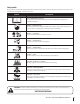
Safety Symbols This page depicts and describes safety symbols that may appear on this product. Read, understand, and follow all instructions on the machine before attempting to assemble and operate. Symbol Description READ THE OPERATOR’S MANUAL(S) Read, understand, and follow all instructions in the manual(s) before attempting to assemble and operate DANGER — ROTATING BLADES To reduce the risk of injury, keep hands and feet away.
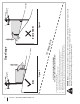
Section 2 — Important Safe Operation Practices Figure 1 line Figure 2 (TOO STEEP) 15° Slope WARNING! Slopes are a major factor related to tip-over and roll-over accidents which can result in severe injury or death. Do not operate machine on slopes in excess of 15 degrees. All slopes require extra caution. Always mow across the face of slopes, never up and down slopes. To check the slope, proceed as follows: 1. Remove this page and fold along the dashed line. 2.
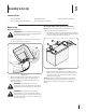
3 Assembly & Set-Up Contents of Crate • One Lawn Mower • • One Lawn Mower Operator’s Manual • One Oil Drain Tube • One Deck Wash Hose Coupler One Engine Operator’s Manual Mower Set-Up Attaching the Battery Cables (for Electric Start Models) Shipping Brace Removal NOTE: The positive battery terminal is marked Pos. (+). The negative battery terminal is marked Neg. (–). WARNING! Make sure the lawn mower’s engine is off. Remove the ignition key (if so equipped) before removing the shipping brace.
Unfolding the Handle Attaching the Shift Lever 1. 1. Remove the star knobs and carriage screws from the lower handle. See Figure 3-3. Figure 3-3 2. Pivot the upper handle into operating position. Be careful not to crimp cables. See Figure 3-4. Remove the screw and the lock nut that secures the shift lever to the shift lever plate. See Figure 3-5. Figure 3-5 2. Remove the remaining screw and nut from the lower shift lever plate. See Figure 3-5. 3.
Checking Tire Pressure WARNING! Under any circumstance do not exceed manufacturer’s recommended psi. Equal tire pressure should be maintained at all times. Refer to sidewall of tire for recommended pressure. The rear tires on your unit may be over-inflated for shipping purposes. Reduce the tire pressure before operating the mower. Refer to the tire side wall for tire manufacturer’s recommended psi and deflate (or inflate) the tires as necessary. Gas and Oil The fuel tank has a capacity of two gallons.
4 Controls and Features Throttle/Choke Control Blade Control Fuel Tank Cap Ignition Switch Deck Height Lever Systems Indicator Monitor Drive Control Gear Shift Lever Figure 4-1 Lawn Mower controls and features are illustrated in Figure 4-1 and described on the following pages. WARNING! Read and follow all safety rules and instructions in this manual, including the entire Operation section, before attempting to operate this machine.
Ignition Switch (Electric Start Models Only) WARNING! Never leave a running machine unattended. Always disengage blades, stop engine and remove key to prevent unintended starting. Run Position Stop Position Blade Control Located on the right-hand handle, the blade control is used to engage the mowing deck. To operate, press and hold the lever against the handlebar grip. To stop the blades, release the blade control. WARNING! Never attempt to start the engine with the blade control engaged.
Systems Indicator Monitor / Hour Meter (Electric Start Models Only) 42. 0 LCD When the ignition key is rotated out of the STOP position but not into the START position, the systems indicator monitor displays the battery’s output, in volts, on its LCD for approximately five seconds, after which it displays an hour glass and the hours of mower operation. Once the engine is started, the monitor continually displays an hour glass and the hours of mower operation on its LCD.
5 Operation Starting the Engine Stopping the Engine WARNING! If you strike a foreign object, stop the engine and remove the ignition key (if so equipped). Thoroughly inspect the machine for any damage. Repair the damage before restarting and operating For Mowers Equipped with Electric Start Refer to the Set-Up and Assembly section of this manual for Gasoline and Oil fill-up instructions. 1. Release all controls on the mower. 2. Move the gear shift lever into the neutral (N) position. 3.
Engaging the Blades WARNING! To help avoid blade contact or a thrown object injury, keep bystanders, helpers, children and pets at least 75 feet from the machine while it is in operation. Stop machine if anyone enters the area. 1. Move the throttle/choke control to the FAST (rabbit) position. 2. Slowly squeeze the Blade Control against the right handle grip and the blades will engage. Release it and the blades will stop. The following information will be helpful when operating your mower.
Installing / Removing Mulch Baffle WARNING! Before installing or removing the mulch plug, disengage blades, stop the engine and remove key if so equipped to prevent unintended starting. Stop the engine and wait for all parts to stop moving. Installing the Mulch Baffle 1. Insert the right-side tab (A) of the baffle into the bracket on the deck. See Figure 5-1. C B A Figure 5-1 2. Insert the mulch baffle into the discharge opening (B), See Figure 5-1. 3.
6 Maintenance & Adjustments Maintenance 4. WARNING! Before performing any maintenance or repairs, disengage blades, stop engine and remove key if so equipped to prevent unintended starting. Pop open the protective cap on the end of the oil drain valve to expose the drain port. See Figure 6-2. Oil Fill Cap/Dipstick Engine Refer to the Engine Owner’s Manual for all engine maintenance procedures and specific instructions pertaining to your engine.
Battery (Electric Start Models Only) 1. CALIFORNIA PROPOSITION 65 WARNING! Battery posts, terminals, and related accessories contain lead and lead compounds, chemicals known to the State of California to cause cancer and reproductive harm. Wash hands after handling. Position the mower on a level, clear spot on your lawn, near enough for your garden hose to reach. CAUTION: Make certain the mower’s discharge chute is directed AWAY from your house, garage, parked cars, etc.
Lubrication Blade Timing Belt WARNING! Before lubricating, repairing, or inspecting, always disengage PTO, set parking brake, stop engine and remove key if so equipped to prevent unintended starting. The cutting deck spindles are driven by timing (cogged) belt, assuring that the deck blades are always perpendicular to each other. At least once a season, or after striking any foreign object, check the timing belt as follows: 1.
2. The top of each spindle pulley is marked with an arrow. See Figure 6-6. The arrows should be perpendicular (at a 90˚ angle) to each other. Adjustments WARNING! Shut the engine off and remove the ignition key (if so equipped) before making adjustments. Handle Height The upper handle is secured to two support bars that can be adjusted to raise or lower the handle height. Adjust if necessary as follows: 1.
Maintenance Schedule Each use or every 5-10 Hrs. Clean Mower Check Engine Oil Level Check Air Filter Every 10 Hours Every season Every season Every season or or or 25 Hours 50 Hours 100 Hours P P P P P Replace Air Filter Element † P Change Engine Oil †† P Clean Battery Terminals P P Lube Front Wheels and Casters Lube Pivot Points Check Spark Plug Condition & Gap P Replace Fuel Filter † Service more frequently when used in dusty areas.
7 Service Cutting Deck Removal WARNING! Before performing any maintenance or repairs, disengage blades, stop engine and remove key if so equipped to prevent unintended starting. To remove the cutting deck, proceed as follows: 1. Remove the belt cover by removing the three screws and washers which secure it to the frame. See Figure 7-1. WARNING: Do not operate mower without the belt cover installed. Failure to follow this instruction could result in personal injury or property damage. Figure 7-2 6.
10. Carefully unhook the mower’s lift assembly from the rear deck supports. 11. Use the deck height lever to raise the lift assembly to its highest position. 12. Remove the wooden blocks from under the deck and gently slide the cutting deck toward the rear of the machine. 13. Pull the click pin out and unhook the drive spring cable from the idler arm assembly. See Figure 7-4. 2. Place a block of wood between the center deck housing baffle and the cutting blade to act as a stabilizer.
WARNING! A poorly balanced blade will cause excessive vibration, may damage the mower and/or result in personal injury. 5. Battery (Electric Start Models Only) CALIFORNIA PROPOSITION 65 WARNING: Battery posts, terminals, and related accessories contain lead and lead compounds, chemicals known to the State of California to cause cancer and reproductive harm. Wash hands after handling. Test the blade’s balance using a blade balancer. Grind metal from the heavy side until it balances evenly.
Changing the Deck Engagement Belt Changing the Deck Timing Belt WARNING! Shut the engine off and remove key if so equipped before removing the cutting blade(s) for sharpening or replacement. Protect your hands by using heavy gloves when grasping blades and pulleys. Several components must be removed and special tools used in order to change the mower deck’s timing belt. See your Cub Cadet dealer to have the deck’s timing belt replaced.
8 Troubleshooting Problem Engine fails to start Cause Remedy 1. Choke not activated. 1. Place throttle/choke control in CHOKE position. 2. Fuel tank empty, or stale fuel. 2. Fill tank with clean, fresh (less than 30 days old) gas. 3. Blocked fuel line. 3. Clean fuel line and replace fuel filter. 4. Faulty spark plug. 4. Clean, adjust gap or replace plug. 5. Engine flooded. 5. Crank engine with throttle in FAST position. 6. Dead battery (electric start models only). 6. Recharge battery. 7.
9 Replacement Parts Component Part Number and Description 951-10292 759-3336 Spark Plug (MTD) Spark Plug (Briggs) (Champion RC12YC) 951-12260 951-12256 BS-797007 Air Filter Cartridge (MTD) Pre-Cleaner (MTD) Air Filter Element (Briggs & Stratton) 951-12182 Fuel Cap 951-3013 BS-394358S Fuel Filter (MTD) Fuel Filter (Briggs & Stratton) 951-12690 BS-492932S Oil Filter (MTD) Oil Filter (Briggs & Stratton) 954-04139 Belt (Mowing Deck Engagement) 942-04154A Deck Blade 734-04263 634-04349 Wheel (Fr
Component Part Number and Description 925-1707D† Battery 946-04604 Throttle/Choke Control (Cable) 925-2054A† Ignition Key 931-04244 Discharge Chute Assembly 631-04252 Mulch Baffle 731-05766 Trail Shield † If Equipped Phone (800) 965-4CUB to order replacement parts or a complete Parts Manual (have your full model number and serial number ready). Parts Manual downloads are also available free of charge at www.cubcadet.com.
10 Attachments & Accessories The following attachments and accessories are compatible for the Cub Cadet Wide Cut Mower. See your Cub Cadet dealer or the retailer from which you purchased your mower for information regarding price and availability.
Notes 11 31
FEDERAL and/or CALIFORNIA EMISSION CONTROL WARRANTY STATEMENT YOUR WARRANTY RIGHTS AND OBLIGATIONS MTD Consumer Group Inc, the United States Environmental Protection Agency (EPA), and for those products certified for sale in the state of California, the California Air Resources Board (CARB) are pleased to explain the emission (evaporative and/or exhaust) control system (ECS) warranty on your 2013 and later small off-road spark-ignited engine and equipment (outdoor equipment engine).
10. Add-on or modified parts that are not exempted by the Air Resources Board may not be used. The use of any non-exempted add-on or modified parts by the ultimate purchaser will be grounds for disallowing a warranty claims. MTD Consumer Group Inc will not be liable to warrant failures of warranted parts caused by the use of a non-exempted add-on or modified part.
CUB CADET LLC MANUFACTURER’S LIMITED WARRANTY FOR 33-INCH WIDE CUT MOWER IMPORTANT: To obtain warranty coverage owner must present an original proof of purchase and applicable maintenance records to the servicing dealer. Please see the operator’s manual for information on required maintenance and service intervals.