Safe Operation Practices • Set-Up • Operation • Maintenance • Service • Troubleshooting • Warranty Operator’s Manual Self Propelled Mower — Model 98M WARNING READ AND FOLLOW ALL SAFETY RULES AND INSTRUCTIONS IN THIS MANUAL BEFORE ATTEMPTING TO OPERATE THIS MACHINE. FAILURE TO COMPLY WITH THESE INSTRUCTIONS MAY RESULT IN PERSONAL INJURY. CUB CADET LLC, P.O. BOX 361131 CLEVELAND, OHIO 44136-0019 Printed In USA Form No.
1 To The Owner Thank You Thank you for purchasing a Lawn Mower manufactured by Cub Cadet LLC. It was carefully engineered to provide excellent performance when properly operated and maintained. Please read this entire manual prior to operating the equipment. It instructs you how to safely and easily set up, operate and maintain your machine. Please be sure that you, and any other persons who will operate the machine, carefully follow the recommended safety practices at all times.
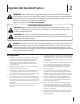
Important Safe Operation Practices 2 WARNING: This symbol points out important safety instructions which, if not followed, could endanger the personal safety and/or property of yourself and others. Read and follow all instructions in this manual before attempting to operate this machine. Failure to comply with these instructions may result in personal injury. When you see this symbol.
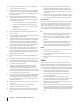
12. A missing or damaged discharge cover can cause blade contact or thrown object injuries. 13. Many injuries occur as a result of the mower being pulled over the foot during a fall caused by slipping or tripping. Do not hold on to the mower if you are falling; release the handle immediately. 14. a. Step back from mower to fully extend your arms. b. Be sure you are well balanced with sure footing. c. Pull the mower back slowly, no more than half way toward you. d. Repeat these steps as needed.
Service 3. Check the blade and engine mounting bolts at frequent intervals for proper tightness. Also, visually inspect blade for damage (e.g., bent, cracked, worn) Replace blade with the original equipment manufacture’s (O.E.M.) blade only, listed in this manual. “Use of parts which do not meet the original equipment specifications may lead to improper performance and compromise safety!” 4. Mower blades are sharp and can cut. Wrap the blade or wear gloves, and use extra caution when servicing them.
Spark Arrestor Average Useful Life Warning: This machine is equipped with an internal combustion engine and should not be used on or near any unimproved forest-covered, brush covered or grass-covered land unless the engine’s exhaust system is equipped with a spark arrester meeting applicable local or state laws (if any). If a spark arrester is used, it should be maintained in effective working order by the operator.
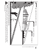
or a corner of a building... a 1 5 ° slop or a fence post ine (r ep r e s e nts dl o n g d otte l Fold a Sight and hold this level with a vertical tree... 15° Use this page as a guide to determine slopes where you may not operate safely. e) WARNING: Do not operate your lawn mower on such slopes. Do not mow on inclines with a slope in excess of 15 degrees (a rise of approximately 2-1/2 feet every 10 feet). A riding mower could overturn and cause serious injury.
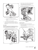
3 Assembly & Set-Up Contents of Carton • One Lawn Mower • One Grass Catcher • One Grass Catcher Adapter • One Side Discharge Chute • One Hardware Pack • One Bottle of Oil • One Lawn Mower Operator’s Manual Assembly 2. NOTE: This unit is shipped without gasoline or oil in the engine. Fill up gasoline and oil as instructed in the accompanying engine manual BEFORE operating your mower. Locate the hairpin clip on the weld pin on each side of lower handle. a. Handle 1.
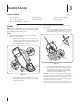
2. Replace with grass bag adapter, while making sure the front lip of adapter goes under the edge of the deck. Secure with wing nuts previously removed. 3. Lift chute door on the grass bag adapter and slide grass bag onto the adapter. See Fig. 3-5. A B C 3 Figure 3-3 4. a. Hold blade control against upper handle. b. Pull starter rope out of the engine. Release blade control. c. Slip starter rope into rope guide. Attach cables to the lower handle with the cable ties already on the lower handle.
Adjustments Drive Control Cutting Height The adjustment wheel is located in the drive control handle housing and is used to tighten or loosen the drive belt. You will have to adjust the drive control if any of the following happens: The cutting height adjustment lever is located above the rear left wheel. See Fig. 3-7A insert. A 2 3 1 B The mower does not propel itself with the drive control engaged. 2. The mower’s drive wheels hesitate with the drive control engaged.
4 Controls and Features Blade Control Drive Control Choke Control Cutting Height Adjustment Lever Recoil Starter Side Discharge Chute Figure 4-1 Blade Control Choke Control The blade control is attached to the upper handle of the mower. Depress and squeeze it against the upper handle to operate the unit. Release it to stop engine and blade. The choke control is located on the left side of the handle and when activated, closes the choke plate on the carburetor and aids in starting the engine.
5 Operation Starting Engine WARNING: Be sure no one other than the operator is standing near the lawn mower while starting engine or operating mower. Never run engine indoors or in enclosed, poorly ventilated areas. Engine exhaust contains carbon monoxide, an odorless and deadly gas. Keep hands, feet, hair and loose clothing away from any moving parts on engine and lawn mower. 1. 1 4 Pull out the choke knob located on the left side of the upper handle. See Fig. 5-1.
6 Maintenance & Adjustments Maintenance 2. Lubricate the wheels and casters at least once a season with light oil (or motor oil). If wheels are removed for any reason, lubricate the axle bolt and inner surface of the wheel with light oil. See Fig. 6-1. General Recommendations • Always observe safety rules when performing any maintenance. 3. • The warranty on this lawn mower does not cover items that have been subjected to operator abuse or negligence.
Engine Care Replacing Rear Flap NOTE: Refer to the Engine Operation and Maintenance sections in this manual for detailed instructions. To replace rear flap, proceed as follows: • Maintain oil level. • Service air cleaner every 25 hours under normal conditions. Clean every few hours under extremely dusty conditions. • Clean spark plug and reset the gap once a season. • Clean engine regularly with a cloth or brush. Keep the area around the top of the engine clean to permit proper air circulation.
7 Service Blade Care WARNING: When removing the cutting blade for sharpening or replacement, protect your hands with a pair of heavy gloves or use a heavy rag to hold the blade. WARNING: An unbalanced blade will cause excessive vibration when rotating at high speeds. It may cause damage to mower and could break causing personal injury. 5. Lubricate the engine crankshaft and the inner surface of the blade adapter with light oil. Slide the blade adapter onto the engine crankshaft.
8 Troubleshooting Problem Engine Fails to start Cause Remedy 1. Blade control disengaged. 1. Engage blade control. 2. Spark plug boot disconnected. 2. Connect wire to spark boot. 3. Fuel tank empty or stale fuel. 3. Fill tank with clean, fresh gasoline. 4. Engine not primed (if equipped with primer). 4. Prime engine as instructed in the Operation section. 5. Faulty spark plug. 5. Clean, adjust gap, or replace. 6. Blocked fuel line. 6. Clean fuel line. 7. Engine flooded. 7.
8 Troubleshooting Problem Uneven cut Mower will not self propel Cause Remedy 1. Wheels not positioned correctly. 1. Place all four wheels in same height position (if equipped with individual height adjusters). 2. Dull blade. 2. Sharpen or replace blade. 1. Belt not installed properly. 1. Check belt for proper pulley installation and movement. 2. Debris clogging drive operation. 2. Stop engine, disconnect spark plug boot, and clean out debris. 3. Damaged or worn belt. 3.
9 Engine Operation Fuel Cap Air Cleaner Starter Grip Oil Fill Cap Oil Drain Spark Plug Figure 10-1 Pre-Operation Check 10w Oil Recommendations 20w NOTE: This engine is shipped without gasoline or oil in the engine. Running the engine with insufficient oil can cause serious engine damage and void the engine warranty. • 1 Before starting engine, fill with oil. Do not over-fill. Oil capacity is about 20 oz.
Check Oil Level Check Fuel Level NOTE: Be sure to check the engine on a level surface with the engine stopped. 1. Clean around fuel fill before removing cap to fuel. 2. Fill tank to approximately 1-inch below lowest portion of neck to allow for fuel expansion. Be careful not to overfill. 1. Remove the oil filler cap and wipe the dipstick clean. See Fig. 10-2. NOTE: Before refueling, allow engine to cool 2 minutes.
10 Engine Maintenance WARNING: Shut off the engine before performing any maintenance. To prevent accidental start-up, disconnect the spark plug boot. IMPORTANT: If engine must be tipped to transport equipment or to inspect or remove grass, keep spark plug side of engine up. Transporting or tipping engine spark plug down may cause smoking, hard starting, spark plug fouling, or oil saturation of air cleaner.
Oil Service Air Cleaner Service • Check oil level regularly. • Be sure correct oil level is maintained. Check every five hours or daily before starting engine. See oil checking procedure in the Operation section. Paper filters cannot be cleaned and must be replaced once a year or every 100 operating hours; more often if used in extremely dusty conditions. WARNING: Never use gasoline or low flash point solvents for cleaning the air cleaner element. A fire or explosion could result.
Spark Plug Service 3. WARNING: DO NOT check for spark with spark plug removed. DO NOT crank engine with spark plug removed. Measure the plug gap with a feeler gauge. Correct as necessary by bending side electrode. See Fig. 10-4. The gap should be set to 0.030 in. To ensure proper engine operation, the spark plug must be properly gapped and free of deposits. 1. Remove the spark plug boot and use a spark plug wrench to remove the plug. See Fig. 10-3. Electrode Spark Plug 0.030 in. Figure 10-4 4.
Fuel Filter Service Storage The fuel filter cannot be cleaned and must be replaced once a year or every 100 operating hours; more often if run with old gasoline. Engines stored between 30 and 90 days need to be treated with a gasoline stabilizer and engines stored over 90 days need to be drained of fuel to prevent deterioration and gum from forming in fuel system or on essential carburetor parts.
The SureStart Guarantee™ Provisions of Your Limited Warranty In addition to the other terms and conditions of the Limited Warranty applicable to your new mower, Cub Cadet LLC (“Cub Cadet”) hereby warrants that your mower’s engine will start on the first or second attempt by an able-bodied adult (subject to the limitations described below) for the duration of the manufacturer’s limited warranty applicable to your product.
Notes 11 25
34 Model 98M 32 1 9 49 5 20 48 12 47 3 11 8 2 46 4 30 45 13 44 43 36 37 38 39 7 42 41 40 6 42 33 35 43 31 15 26 29 10 10 27 28 24 25 22 21 14 19 23 26 18 17 16
Model 98M Ref No. Part Number Description Ref No. Part Number Description 1 747-1161A Blade Control 26 664-0180 Grass Bag Assembly 2 710-1270 Machine Screw, 1/4-20 x 1.310 27 731-1832 Side Discharge Chute 3 712-04063 Flange Lock Nut, 5/16-18 28 782-9063 Belt Keeper 4 726-0240 Cable Tie 29 754-0460 V-Belt 5 746-04431 Control Cable 30 710-04744 Screw, #12-16 x 1.00 6 710-0654A TT Screw, 3/8-16 x 1.
Model 98M 12 6 22 27 23 34 37 1 2 32 59 29 30 36 26 28 45 42 55 31 56 41 7 23 9 11 13 18 38 39 48 23 17 55 46 52 49 51 12 8 54 5 3 4 33 50 57 28 16 30 10 14 48 53 35 40 23 25 24 44 6 20 21 47 43 14 13 58 56 19 15
Model 98M Ref No. Part Number Description Ref No. Part Number Description 1 714-0474 Cotter Pin 29 682-7528 Chain Cover Assembly 2 710-1652 Screw 1/4-14 x .825 30 741-0324A Flge Bearing .506 ID x .590 Lg 3 736-0264 Flat Washer.330 ID x.630 OD 31 682-7526 Transmission Axle Assembly 4 714-0104 Cotter Pin 32 618-0263A Transmission Ass’y Complete 5 732-0306 Compression Spring 33 734-1857 Wheel 7 x 2 6 734-2044 Wheel, 9 x 2.
Engine Model - 1P70 21 29 8 9 15 20 1 7 3 13 2 19 18 24 25 11 26 17 10 17 6 28 4 5 12 14 27 22 23 16 30
Engine Model - 1P70 Ref No. Part Number 1. 951-10368 Fuel Tank 2. 951-10369 Flywheel Shroud 3. 951-10335 Rubber Fuel Tank Mounting Washer 4. 951-10334 Oil Filler Tube Assembly 5. 951-10333 Dipstick Assembly 6. 951-10413 Cylinder Head Complete 7. 951-10414 Short Block Assembly 8. 951-10321 Stop Switch and Brake Assembly 9. 951-10319 Recoil Spring and Pulley Assembly 10. 951-10344 Push Rod Kit 11. 951-10345 Valve Kit 12. 951-10370 Oil Drain Plug and Washer Assembly 13.
Cub Cadet LLC (Cub Cadet), The United States Environment Protection Agency (U. S. EPA) Emission Control System Warranty Statement (Owner’s Defect Warranty Rights and Obligations) The U. S. EPA and Cub Cadet are pleased to explain the emissions control system warranty on your model year 2005 and later small off-road engine. New small off-road engines must be designed, built and equipped to meet the stringent anti-smog standards.
(7) The engine manufacturer is liable for damages to other engine components proximately caused by a failure under warranty of any warranted part. (8) Throughout the engine’s warranty period defined in Subsection (a)(2), Cub Cadet will maintain a supply of warranted parts sufficient to meet the expected demand for such parts. (9) Any replacement part may be used in the performance of any warranty maintenance or repairs and must be provided without charge to the owner.
Notes 34
Notes 35
CUB CADET LLC MANUFACTURER’S LIMITED WARRANTY FOR walk-behind mowerS IMPORTANT: To obtain warranty coverage owner must present an original proof of purchase and applicable maintenance records to the servicing dealer. Please see the operator’s manual for information on required maintenance and service intervals.