Safe Operation Practices • Set-Up • Operation • Maintenance • Service • Troubleshooting • Warranty Operator’s Manual Yard Vacuum/Chipper/Shredder with Vacuum/Hose Model CSV 050 WARNING READ AND FOLLOW ALL SAFETY RULES AND INSTRUCTIONS IN THIS MANUAL BEFORE ATTEMPTING TO OPERATE THIS MACHINE. FAILURE TO COMPLY WITH THESE INSTRUCTIONS MAY RESULT IN PERSONAL INJURY. CUB CADET LLC, P.O. BOX 361131 CLEVELAND, OHIO 44136-0019 Printed In USA Form No.
1 To The Owner Thank You Thank you for purchasing a Chipper/Shredder Vacuum manufactured by Cub Cadet LLC. It was carefully engineered to provide excellent performance when properly operated and maintained. Please read this entire manual prior to operating the equipment. It instructs you how to safely and easily set up, operate and maintain your machine. Please be sure that you, and any other persons who will operate the machine, carefully follow the recommended safety practices at all times.
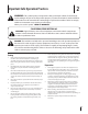
Important Safe Operation Practices 2 WARNING: This symbol points out important safety instructions which, if not followed, could endanger the personal safety and/or property of yourself and others. Read and follow all instructions in this manual before attempting to operate this machine. Failure to comply with these instructions may result in personal injury.
Safe Handling of Gasoline: 4. To avoid personal injury or property damage use extreme care in handling gasoline. Gasoline is extremely flammable and the vapors are explosive. Serious personal injury can occur when gasoline is spilled on yourself or your clothes which can ignite. Wash your skin and change clothes immediately. 1. Use only an approved gasoline container. 2. Never fill containers inside a vehicle or on a truck or trailer bed with a plastic liner.
Maintenance & Storage Do not modify engine 1. Never tamper with safety devices. Check their proper operation regularly. 2. Check bolts and screws for proper tightness at frequent intervals to keep the machine in safe working condition. Also, visually inspect machine for any damage and repair, if needed. To avoid serious injury or death, do not modify engine in any way. Tampering with the governor setting can lead to a runaway engine and cause it to operate at unsafe speeds.
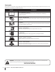
Safety Symbols This page depicts and describes safety symbols that may appear on this product. Read, understand, and follow all instructions on the machine before attempting to assemble and operate. Symbol Description READ THE OPERATOR’S MANUAL(S) Read, understand, and follow all instructions in the manual(s) before attempting to assemble and operate WARNING— ROTATING BLADES Keep hands out of inlet and discharge openings while machine is running.
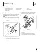
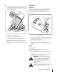
3 Assembly & Set-Up Contents of Carton • One Chipper/Shredder Vacuum • One Operator’s Manual • One Bag • One Upper and Lower Handle • One Hose Assembly • One Safety Glasses • One Bottle of Oil Assembly 2. NOTE: This unit is shipped without gasoline or oil in the engine. Fill up gasoline and oil as instructed in the accompanying engine manual BEFORE operating your chipper shredder vacuum. Unfold the upper handle until it aligns with lower handle.
4. Pull the two cable ties attached to the cables tight approximately 8 inches from each cable end and place the cables into the cable guide. 2. Pull spring loaded pin out on the base and align pin with the first hole (closest to the end of the tube) in the hose adapter. See Fig. 3-4B. 5. Loosen the wing nut that secures the rope guide to the right side of upper handle. 3. Release the pin to lock the hose in place. 4.
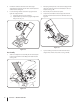
Adjustments Bag 1. Grasp bag handle with one hand and slide locking rod on mounting bracket with other hand toward engine. Use the end of mounting bracket as leverage when sliding the locking rod. See Fig. 3-6. Nozzle Height The nozzle can be adjusted to any six positions, ranging from 5/8” to 4 1/8” ground clearance. The nozzle height has to be adjusted according to chipper shredder conditions. 1. 3 Depress nozzle height adjustment lever towards wheel. See Fig. 3-7. 2 2 1 4 3 1 Figure 3-6 2.
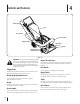
4 Controls and Features Recoil Starter Bag Hose Handle Hose Assembly Chipper Chute Nozzle/Hose Vac Lever Nozzle Nozzle Height Adjustment Lever Figure 4-1 WARNING: The operation of any chipper shredder can result in foreign objects being thrown into the eyes, which can damage your eyes severely. Always wear the safety glasses provided with this unit or eye shields while operating or while performing any adjustments or repairs.
5 Operation Starting Engine Stopping Engine 1. 1. Turn off the engine switch. 2. Disconnect spark plug wire and ground against the engine to prevent unintended starting. Pull out the choke knob located on the engine. See Fig. 5-1 inset. NOTE: Use of the choke may not be necessary if the engine is warm or the air temperature is high. To Empty Bag 1. Unhook bag straps from the lower handle. 2. Unsnap bag clip from the top of lower handle. See Fig. 5-2. 2 1 2 4 3 3 Figure 5-1 2.
Buttons Inner Flap Outer Flap Figure 5-3 8. Twist the buttons to lock bag. Place bag back onto unit as instructed in Assembly & Set-Up. WARNING: Do not at any time make any Figure 5-4 Using The Hose Assembly 1. adjustments without first stopping engine and disconnecting spark plug wire. Place nozzle/hose vac lever in the bottom position on the nozzle to redirect vacuum to the hose assembly. See Fig. 5-5.
6 Maintenance & Adjustments Maintenance Equipment Care General Recommendations • Clean the chipper/shredder vacuum thoroughly after each use. • Always observe safety rules when performing any maintenance. • Wash bag periodically with water. Allow to dry thoroughly in shade. • The warranty on this chipper/shredder vacuum does not cover items that have been subjected to operator abuse or negligence. To receive full value from warranty, operator must maintain the equipment as instructed here.
WARNING: Before performing any type of maintenance on the machine, wait for all parts to stop moving and disconnect the spark plug wire. Failure to follow this instruction could result in personal injury or property damage. 6. Remove and clean the screen by scraping or washing with water. See Fig. 6-3. Removing the Flail Screen If the discharge area becomes clogged, remove the flail screen and clean area as follows: 1. Stop the engine.
7 Service Blade Care Front Support Brace/ Lock Nut WARNING: Before performing any type of maintenance on the machine, wait for all parts to stop moving and disconnect the spark plug wire. Failure to follow this instruction could result in personal injury or property damage. Bell Washer Thrust Washer NOTE: When tipping the unit, empty the oil and fuel tank and keep engine spark plug side up. 1. Disconnect and ground the spark plug wire to retaining post. 2. Remove bag assembly or blower chute. 3.
7. Carefully tilt and support the unit up to provide access underneath to the nozzle mounting hardware and impeller. Remove the three shoulder bolts securing the black plastic lower flail housing to the lower housing. Refer to Fig. 7-4. 10. The nuts on the flat head cap screws can be reached from underneath using a 1/2-inch socket, universal, and extension. See Fig. 7-6. Impeller Nuts Figure 7-6 Figure 7-4 8. Tilt top of black plastic lower flail housing toward the engine to remove. 9.
8 Troubleshooting Problem Engine Fails to start Cause Remedy 1. Throttle lever (if equipped) not in correct starting position. 1. Move throttle lever to FAST or START position. 2. Engine switch (if equipped) in OFF position. 2. Move engine switch to ON position. 3. Spark plug wire disconnected. 3. Connect wire to spark plug. 4. Choke not in CHOKE position (if equipped). 4. Move choke lever to CHOKE position. 5. Fuel tank empty or stale fuel. 5. Fill tank with clean, fresh gasoline. 6.
9 Engine Operation Fuel Cap Air Cleaner Starter Grip Oil Fill Cap Spark Plug Figure 9-1 Pre-Operation Check 10w Oil Recommendations 20w NOTE: This engine is shipped without gasoline or oil in the engine. Running the engine with insufficient oil can cause serious engine damage and void the engine warranty. • 1 Before starting engine, fill with oil. Do not over-fill. Oil capacity is about 20 oz.
Check Oil Level Check Fuel Level NOTE: Be sure to check the engine on a level surface with the engine stopped. 1. Clean around fuel fill before removing cap to fuel. 2. Fill tank to approximately 1-inch below lowest portion of neck to allow for fuel expansion. Be careful not to overfill. 1. Remove the oil filler cap and wipe the dipstick clean. See Fig. 9-2. NOTE: Before refueling, allow engine to cool 2 minutes.
10 Engine Maintenance WARNING: Shut off the engine before performing any maintenance. To prevent accidental start-up, disconnect the spark plug boot. IMPORTANT: If engine must be tipped to transport equipment or to inspect or remove grass, keep spark plug side of engine up. Transporting or tipping engine spark plug down may cause smoking, hard starting, spark plug fouling, or oil saturation of air cleaner.
Oil Service Air Cleaner Service • Check oil level regularly. • Be sure correct oil level is maintained. Check every five hours or daily before starting engine. See oil checking procedure in the Operation section. Paper filters cannot be cleaned and must be replaced once a year or every 100 operating hours; more often if used in extremely dusty conditions. WARNING: Never use gasoline or low flash point solvents for cleaning the air cleaner element. A fire or explosion could result.
Spark Plug Service 3. WARNING: DO NOT check for spark with spark plug removed. DO NOT crank engine with spark plug removed. Measure the plug gap with a feeler gauge. Correct as necessary by bending side electrode. See Fig. 10-4. The gap should be set to 0.030 in. To ensure proper engine operation, the spark plug must be properly gapped and free of deposits. 1. Remove the spark plug boot and use a spark plug wrench to remove the plug. See Fig. 10-3. Electrode Spark Plug 0.030 in. Figure 10-4 4.
Fuel Filter Service Storage The fuel filter cannot be cleaned and must be replaced once a year or every 100 operating hours; more often if run with old gasoline. Engines stored between 30 and 90 days need to be treated with a gasoline stabilizer and engines stored over 90 days need to be drained of fuel to prevent deterioration and gum from forming in fuel system or on essential carburetor parts.
Model CSV 050 2 54 8 6 53 5 34 9 3 11 34 7 22 10 12 17 36 50 18 4 20 14 16 13 15 20 56 27 57 24 20 38 7 55 40 37 21 44 41 25 26 51 43 52 28 48 29 30 50 50 46 33 39 1 47 35 42 45 49 31 28 32 24 23 19
Model CSV 050 Ref No. Part Number Description Ref No. Part Number Description 1 736-0314 Thrust Washer.375 ID x.70 OD 30 764-0648A Vacuum Hose 2 749-04172 Upper Handle 31 720-0369 Handle Plug 3 720-0279 Knob 32 731-06469 Hose Adapter 4 710-0599 Screw, 1/4-20 x.500 33 712-0442 Cap Lock Nut, 1/4-20 5 710-1205 Eye Bolt 34 710-1611B TT Screw, 5/16-18 x .750 6 781-1056 Upper Handle Bracket 35 781-04082 Front Wheel Support Brace 7 710-0726 Hex Cap Screw 5/16-12 x.
Model CSV 050 34 35 37 36 38 30 1 39 40 42 41 44 48 43 44 30 46 28 44 29 B 47 49 45 11 4 2 3 15 11 10 9 31 33 8 7 16 B 13 5 32 19 6 A 22 23 17 A 24 14 12 25 26 21 20 27 26 18
Model CSV 050 Ref No. Part Number Description Ref No. Part Number Description 26 732-1151A Nozzle Door Torsion Spring Screen Assembly 27 731-2294A Nozzle Door Hex Screw 5/16-24 x 1.0 28 664-04040 Bag 781-0490 Chipper Blade 29 631-0083 Chute Assembly 5 781-0735 Pin Clip 30 710-0726 Hex Index Screw, 5/16-12 x.750 6 719-0329 Flail 31 736-0247 Flat Washer.375 ID x 1.
Engine Model - 1P70CO 21 29 15 8 9 29 20 30 1 7 3 2 19 13 18 24 17 25 31 26 28 10 11 6 5 4 12 14 27 32 23 16 28 22
Engine Model - 1P70CO Ref No. Part Number 1. 751-10368 Fuel Tank 2. 751-10369 Flywheel Shroud 3. 751-10335 Rubber Fuel Tank Mounting Washer 4. 751-10334 Oil Filler Tube Assembly 5. 751-10852 Dipstick Assembly 6. 751-10413 Cylinder Head Complete 7. 751-10932 Short Block Assembly 8. 751-10936 On/Off Switch and Bracket Assembly 9. 751-10319 Recoil Spring and Pulley Assembly 10. 751-10344 Push Rod Kit 11. 751-10345 Valve Kit 12.
Cub Cadet LLC (Cub Cadet), the California Air Resources Board (CARB) and the United States Environment Protection Agency (U. S. EPA) Emission Control System Warranty Statement (Owner’s Defect Warranty Rights and Obligations) EMISSION CONTROL SYSTEM COVERAGE IS APPLICABLE TO CERTIFIED ENGINES PURCHASED IN CALIFORNIA IN 2005 AND THEREAFTER, WHICH ARE USED IN CALIFORNIA, AND TO CERTIFIED MODEL YEAR 2005 AND LATER ENGINES WHICH ARE PURCHASED AND USED ELSEWHERE IN THE UNITED STATES.
(4) Repair or replacement of any warranted part under the warranty provisions of this article must be performed at no charge to the owner at a warranty station. (5) Notwithstanding the provisions of Subsection (4) above, warranty services or repairs must be provided at all Cub Cadet LLC distribution centers that are franchised to service the subject engines.
CUB CADET LLC MANUFACTURER’S LIMITED WARRANTY FOR Chipper-shredders & Chipper-shredder VACUUMs The limited warranty set forth below is given by Cub Cadet LLC with respect to new merchandise purchased and used in the United States, its possessions and territories, and by MTD Products Limited with respect to new merchandise purchased and used in Canada and/or its territories and possessions. c.
Medidas importantes de seguridad • Configuración • Funcionamiento • Mantenimiento • Servicio • Solución de problemas • Garantía Manual del operador Aspiradora Para Patios — Modelo CSV 050 ADVERTENCIA LEA Y SIGA TODAS LAS INSTRUCCIONES DE ESTE MANUAL ANTES DE PONER EN FUNCIONAMIENTO ESTA MÁQUINA. SI NO RESPETA ESTAS INSTRUCCIONES PUEDE PROVOCAR LESIONES PERSONALES. CUB CADET LLC, P.O. BOX 361131 CLEVELAND, OHIO 44136-0019 Impreso en Estados Unidos de América Form No.
Al propietario 1 Gracias Gracias por comprar una máquina podadora fabricada por Cub Cadet LLC LLC. La misma ha sido diseñada cuidadosamente para brindar excelente rendimiento si se la opera y mantiene correctamente. Por favor lea todo este manual antes de operar el equipo. Le indica cómo configurar, operar y mantener la máquina con seguridad y fácilmente.
Medidas importantes de seguridad ADVERTENCIA: La presencia de este símbolo indica que se trata de instrucciones 2 importantes de seguridad que se deben respetar para evitar poner en peligro su seguridad personal y/o material y la de otras personas. Lea y siga todas las instrucciones de este manual antes de poner en funcionamiento esta máquina. Si no respeta estas instrucciones puede provocar lesiones personales.
Manejo seguro de la gasolina 4. Para evitar lesiones personales o daños materiales sea sumamente cuidadoso al manipular la gasolina. La gasolina es altamente inflamable y sus vapores pueden causar explosiones. Se puede lesionar gravemente si derrama gasolina sobre usted o sobre la ropa ya que se puede encender. Lávese la piel y cámbiese de ropa de inmediato. a. Inspeccione la máquina para ver si está dañada. Utilice sólo recipientes para gasolina autorizados. b. Repare o reemplace las piezas dañadas.
Mantenimiento y almacenamiento Aviso referido a emisiones 1. Nunca manipule los dispositivos de seguridad de manera imprudente. Controle periódicamente que funcionen de forma adecuada. 2. Controle frecuentemente que todos los pernos y tornillos estén bien ajustados para comprobar que la máquina se encuentra en condiciones seguras de funcionamiento. Además, realice una inspección visual de la máquina para controlar si la misma está dañada y repárela de ser necesario.
Símbolos De Seguridad Esta página representa y describe la seguridad los símbolos que pueden parecer en este producto. Lea, comprenda, y siga todas instrucciones en la máquina antes procurar para reunir y operar. Símbolo Descripción LEA EL MANUAL(S) DEL OPERADOR Lea, comprenda, y siga todas instrucciones en el manual (manuales) antes procurar para reunir y operar ADVERTENCIA— GIRANDO HOJAS Mantenga manos fuera de aperturas de cala y descarga mientras máquina corre.
3 Montaje y Configuración Contenido de la caja • Una Aspiradora Para Patios • Uno Manual de Operador • Una Bolsa • Una Manija superior e inferior • Uno Montaje de la manguera • Uno Anteojos de seguridad • Uno Botella del Aceite Montaje 2. NOTA: Esta unidad se envía sin gasolina ni aceite en el motor. Llene con gasolina y aceite como se indica en las instrucciones que se incluyen en el manual de motor adjunto ANTES de poner en funcionamiento su aspiradora para patios.
4. Tire de las dos uniones del cable unidas a los cables, ajuste aproximadamente 8 pulgadas de cada extremo de cable, y ubique los cables en su guía. 5. Afloje la tuerca de mariposa que sostiene la guía de la cuerd contra el lado derecho de la manija superior. a. Tire lentamente de la cuerda de arranque para sacarla del motor. b. Deslice la cuerda de arranque en la guía. Ajuste la tuerca a mariposa. Vea la fig. 3-3. 2.
Bolsa 1. 1. Sostenga la manija de la bolsa con una mano y deslice la varilla de seguridad del soporte de montaje hacia el motor con la otra mano. Use el extremo del soporte de montaje como palanca cuando deslice la varilla de seguridad. Vea la fig. 3-6. Oprima la palanca de ajuste de la altura del pico hacia la rueda. Vea la fig. 3-7. 3 2 3 1 2 Figura 3-7 1 4 Figura 3-6 2. Mueva la palanca de ajuste de altura hacia delante o hacia atrás, para mover el pico arriba o abajo.
4 Controles Y Características Arrancador de Retroceso Bolsa Manija de la manguera Montaje de la manguera Palanca del pico / manguera de la aspiradora Canal de la cortadora Palanca Palanca de ajuste de la altura del pico Figura 4-1 ADVERTENCIA: Al operar una cortadora trituradora puede ser que objetos extraños sean arrojados a los ojos lo cual puede dañarlos gravemente.
5 Funcionamiento Encendido del Motor 1. ADVERTENCIA: Nunca dirijas el motor dentro o en un área mal ventilada. Los gases de combustión de motor contienen el monóxido de carbono, un gas inodoro y mortal. Tire de la perilla del cebador ubicada en el motor. Vea el recuadro de la Fig. 5-1. NOTA: Puede no ser necesario usar el cebador si el motor está caliente o la temperatura del aire es elevada. 2 1 Para Detener El Motor 1. Apague el interruptor del motor. 2.
Botones Aleta Exterior 6. Aleta Interior Figura 5-3 Comprima la abertura de la bolsa y doble la aleta interior sobre la abertura. 7. Doble la aleta exterior sobre la aleta interior e inserte los botones de la bolsa a través de las salidas metálicas. Vea la fig. 5-3. 8. Gire los botones para cerrar la bolsa. Ubique la bolsa de nuevo en la unidad como se indica en Ensamblado y Configuración . Figura 5-4 IMPORTANTE: La pantalla de desgranado está ubicada dentro de la caja en la zona de descarga.
6 Mantenimiento Y Ajustes Mantenimiento 5. Recomendaciones Generales • Respete siempre las reglas de seguridad cuando realice tareas de mantenimiento. • La garantía de esta aspiradora para patios no cubre elementos que han estado sujetos al mal uso o la negligencia del operador. Para recibir el reembolso total de la garantía, el operador deberá dar mantenimiento al equipo como se indica en este manual. Siga el manual de motor separado embalado por su unidad para instrucciones de lubricación.
ADVERTENCIA: Antes de realizarcualquier tipo del mantenimiento en la máquina, espere todas las partes a dejar de moverse y desconectar el alambre de bujía. El fracaso de seguir esta instrucción podría causar la herida personal o el daño a la propiedad. 5. Saque el tornillo de cabeza hexagonal de la parte superior de la caja posterior cerca del soporte de montaje, y la tuerca de seguridad de la brida que une la pantalla de desgranado. Vea la fig. 6-2. 6.
7 Servicio Cuidado de la Cuchilla Traba de sostén delantera/ Arandela Montaje tuerca de seguridad de del brazo campana giratorio ADVERTENCIA: Antes de realizarcualquier tipo del mantenimiento en la máquina, espere todas las partes a dejar de moverse y desconectar el alambre de bujía. El fracaso de seguir esta instrucción podría causar la herida personal o el daño a la propiedad.
7. Incline la unidad con cuidado y apóyela hacia arriba para obtener acceso por la parte inferior al material de montaje del pico y al motor. Retire los tres tornillos con reborde que aseguran el pico de plástico negro a la caja inferior. Consulte la fig. 7-4. 10. Es posible alcanzar las tuercas de los tornillos de cabeza plana desde la parte inferior, mediante una llave universal de 1/2 pulg. con extensión. Vea la fig. 7-6. Motor Tuercas Figure 7-6 Figure 7-4 8.
8 Solución de problemas Problema El motor no arranca El motor funciona de manera errática El motor recalienta Causa Remedio 1. La palanca del regulador (de ser equipado) no está en la posición de arranque correcta. 1. Mueva la palanca del regulador a la posición START (inicio)/RUN (dirigido). 2. Interruptor de motor (de ser equipado) en de posición. 2. Mueva el interruptor de motor a EN la posición. 3. La palanca de obturación no está en la posición ON (encendido). 3.
Problema Causa Saltos ocasionales (pausas) a alta velocidad Demasiada vibración La unidad no descarga La tasa de descarga se reduce de manera considerable o cambia la composición del material descargado 18 Remedio 1. La distancia disruptiva de la bujía es muy pequeña. 1. Quite la bujía y ajuste el hueco. 2. Ajuste de la mezcla del carburador mal realizada. 2. Consulte el manual del motor. 1. Hay partes que están flojas o el motor está dañado. 1.
9 Funcionamiento de Motor Tapón de combustible Depurador de aire Empuñadura del arranque Tapón de llenado de aceite Bujía de encendido Silenciador Figura 9-1 Control Previo al Funcionamiento 10w Recomendaciones Sobre el Aceite 20w IMPORTANTE: Este motor se despacha sin gasolina ni aceite en el motor. Hacer funcionar el motor sin suficiente aceite puede causarle graves daños y anula la garantía del motor. • 1 Antes de arrancar el motor, llene con aceite. No llene en exceso.
Verifique el Nivel de Combustible Tapón de llenado /varilla del nivel de aceite 1. Antes de sacar la tapa para cargar combustible, limpie alrededor. 2. Llene el tanque hasta aproximadamente 1 pulgada debajo de la parte más baja del cuello para permitir la expansión del combustible. Tenga cuidado de no llenar en exceso. IMPORTANTE: Antes de cargar, deje que el motor se enfríe 2 minutos. Encendido del Motor ADVERTENCIA: Siempre mantenga las manos y los pies alejados de las piezas móviles del equipo.
10 Mantenimiento de Motor ADVERTENCIA: Apague el motor antes de realizar el mantenimiento. Para evitar una puesta en marcha accidental, desconecte la funda de la bujía. IMPORTANTE: Si el motor debe inclinarse para transportar equipo o para inspeccionar o extraer pasto, mantenga el lado de la bujía del motor hacia arriba. Si la bujía del motor se transporta o se inclina hacia abajo puede causar humo, un arranque difícil, contaminación de la bujía o saturación con aceite del depurador de aire.
Mantenimiento del aceite • Inspeccione el nivel de aceite regularmente. • Asegúrese de que se mantenga el nivel de aceite correcto. Inspeccione cada cinco horas o diariamente antes de poner en marcha el motor. Cambio de aceite IMPORTANTE: Asegúrese de inspeccionar el motor sobre una superficie nivelada y con el motor apagado. Drene el aceite mientras el motor esté caliente para asegurar un drenaje rápido y completo. 1.
Mantenimiento de Bujía 3. ADVERTENCIA: NO pruebe la chispasi no está la bujía de encendido. NO de arranque al motor si no está la bujía de encendido. Mida la separación de bujía con un calibrador. Corrija de ser necesario torciendo el electrodo lateral. Vea la fig. 10-4. La separación debe establecerse en 0,030 pulg. Para asegurarse de que el motor funcione bien, la bujía debe tener una separación correcta y debe estar libre de depósitos. 1.
Servicio con Filtro de Combustible Almacenamiento El filtro de combustible no puede ser limpiado y debe ser sustituido una vez al año o cada 100 horas de operaciones; más a menudo de ser dirigido con vieja gasolina.
Notas 25
Cub Cadet LLC (Cub Cadet), el Bordo de Recursos de Aire de California (CARB), y la Agencia de Protección Medioambiental de Estados Unidos (U. S.
al efecto de “reparación o reemplazo según sea necesario” no reducirá el período de cobertura de la garantía. Cualquier pieza reparada o reemplazada según la garantía se garantizará por el resto del período de garantía. (3) Cualquier pieza garantizada que esté programada para reemplazo según el mantenimiento requerido de conformidad con las instrucciones escritas de la Subsección (c) se garantiza por el período de tiempo anterior a la primera fecha de reemplazo programada para esa pieza.
GARANTÍA LIMITADA DE CUB CADET LLC PARA cortadoras trituradoras y aspiradoras para cortadoras trituradoras La siguiente garantía limitada es otorgada por Cub Cadet LLC con respecto a nuevos productos adquiridos y utilizados en Estados Unidos, sus posesiones territorios, y por MTD Products Limited con respecto a nuevos productos adquiridos y utilizados en Canadá y/o sus territorios y posesiones. c.