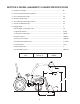
Operator’s Manual Front Loader w/60" Bucket Model 59A40003727 Cub Cadet Yanmar LLC P.O. Box 361052 Cleveland, Ohio 44136-1052 PRINTED IN U.S.A.
Table of Contents Content Page Safe Operation Practices................................................................................................................................. 3 Safety Labels found on the Loader ................................................................................................................. 6 Loader Specifications ...................................................................................................................................... 7 To the Dealer...
section 1: safe operation practices Warning: This symbol points out important safety instructions which, if not followed, could endanger the personal safety and/or property of yourself and others. Read and follow all instructions in this manual before attempting to operate this machine. Failure to comply with these instructions may result in personal injury. When you see this symbol—HEED ITS WARNING. Danger: This machine was built to be operated according to the rules for safe operation in this manual.
10. Your Cub Cadet Yanmar dealer can supply original equipment hydraulic accessories and repair parts. Substitute parts may not meet original equipment specifications and may be dangerous. 17. Stop the loader arms gradually when lowering or lifting. 11. Ensure implement is properly attached, adjusted and in good operating condition. • Move and turn tractor at low speeds. • Watch for hidden hazards such as holes, ditches, and other obstructions which may cause tractor and loader to tip over.
MAINTENANCE 9. Ensure all safety labels are installed. Replace if damaged. (See Safety Labels later in this section) 1. Before dismounting tractor or performing any service or maintenance, disengage power to implement, lower the 3point hitch and all raised components to the ground, operate valve levers to release any hydraulic pressure, stop engine, set parking brake, remove key, and unfasten seat belt. 10. Ensure shields and guards are properly installed and in good condition. Replace if damaged. 11.
Section 2: labels found on loader (QTY 2) 777D11290 On Both Sides 777D11356 777I22804 FLOAT DOWN & CURL (QTY 2) 777I22850 3 DOWN & DUMP DOWN 1 CURL On Both Sides N DUMP 2 UP UP & CURL 4 UP & DUMP READ OPERATORS MANUAL BEFORE OPERATING BUCKET LEVEL REFERENCE POINT 777S32188 WARNING 1. read and undersTand operaTor's Manual before operaTing. 2. keep oTHers aWaY WHen operaTing loader. 3. do noT alloW CHildren or unTrained persons To operaTe eQuipMenT. 4.
section 3: model 59A40003727 loader specifications A Maximum Lift Height................................................................................................... 96” B Clearance With Attachment Dumped.......................................................................... 77” C Reach At Maximum Height......................................................................................... 26” D Maximum Dump Angle.............................................................................
Section 4: TO THE dealer Assembly and proper installation of this attachment is the responsibility of the Cub Cadet Yanmar dealer. Read the instructions and safety precautions found in this manual carefully. Any and all front-end attachments installed on the tractor must first be removed in order to properly install the Front-end Loader. Section 5: TO THE OWNER Model 59A40003727 Front-end Loader is designed for use only with specific Cub Cadet Yanmar tractor models.
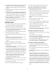
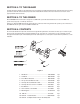
Section 7: unpacking the loader Bucket Assembly Boom & Mast Assembly RH Mount LH Mount Loader Hitch Bracket Front Mount Receiver/ Mounting & Lynch Pins Figure 2 Move the tractor and front loader to an area large enough to accommodate both, and with access to an overhead lift. To uncrate the loader and all components, refer to Figure 2 and proceed as follows: • Carefully remove the top and sides of the shipping crate and carefully cut off the plastic wrapping.
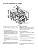
Section 8: Initial Installation Tractor Preparation Remove the front weight bracket from the front of the tractor by removing the six hex screws and nuts securing it to the front frame. Store the front weight bracket for reinstallation when removing the loader and attaching rear mounted equipment. Installing the LH and RH Mounts • From the left side of the tractor, locate the mounting holes and remove the protective plugs.
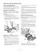
Front Loader Preparation • Mounting the Bucket NOTE: The pistons of the two bucket cylinders may be retracted too far to connect the cylinders to the bucket rear mounting brackets by simply rolling back the bucket and/or manually extending the cylinder pistons. If the cylinders cannot be connected to the bucket now, wait until the hydraulic hoses are connected to extend the cylinder pistons.
Outlet #3 (upper right) - connect the hydraulic line from the piston ends of the boom cylinders (lower boom). Outlet #4 (lower right) - connect the hydraulic line from the cylinder body ends of the boom cylinders (raise boom).
• • Continue to carefully extend the boom cylinders (and roll back the bucket if necessary) until the center points of the support plates on the bottom of the loader hitch bracket at the front of loader hitch arms are resting on the ground (Refer to Figure 13). The support plates and bucket should be supporting the loader and the bottom of each mast should now be higher than the tubular bars of the loader mounts. • Stop the tractor engine and engage the parking brake.
LH Mast Front Mount Receiver Mounting Pin LH Mount Lynch Pin Support Plate Loader Hitch Bracket Figure 11 • When the masts are firmly settled into the tower mounts, continue to slowly push the control lever forward, and to the right, to raise the loader hitch bracket upward into the front mount receiver. As the loader hitch bracket is raised, the boom cylinder pivot pins should also rotate back into the notches of the RH and LH mounts. Refer to Figure 11. Drive the tractor forward as necessary.
section 9: dismounting and mounting the loader Dismounting the Loader • Continue raising the boom until center points of the support plates on the bottom of the loader hitch bracket are resting on the ground, the loader hitch arms and bucket are supporting the weight of the loader, and the bottom of the RH and LH masts have lifted off the tubular bars of the RH and LH mounts. Refer to Figure 13. • Stop the tractor engine and engage the parking brake.
Mounting the Loader • Re-start the tractor engine. With completion of the initial installation and operation, all loader cylinders should be filled with hydraulic oil and should maintain the position of the boom and mast when dismounted. NOTE: If the loader is in storage for an extended period of time, it may become necessary to again raise the base of the masts to re-mount the loader.
section 10: operation Pre-Operation Check List (Operator’s Responsibility) added to your tires, and for any special maintenance instructions after the procedure is performed. The operator should perform the following check list before operating loader. • Review and follow all safety rules and safety labels on pages 3 through 5. • Check that all safety labels are installed and in good condition. Replace if damaged.
Operating the Loader NOTE: Do not be concerned if the bucket is not completely filled during each pass. Maximum productivity is determined by the amount of material loaded in a given period of time. Time is lost if two or more attempts are made to fill the bucket on each pass. WARNING: Do not operate unless all control lever positions function as instructed in Figure 10. The loader should be operated with the tractor engine running at a safe RPM.
Dumping the Bucket Use extreme care when operating the loader on a slope; keep the bucket as low as possible. This keeps the bucket and tractor center of gravity low and will provide maximum tractor stability. See Figure 19. Lift the bucket high enough to clear the side of the vehicle. Move the tractor in as close as possible, then dump the bucket. See Figure 20.
Operating with a Float Control Peeling and Scraping During hard surface operation, keep the bucket level and put the lift control in the float position to permit the bucket to float on the working surface. If hydraulic down pressure is exerted on the bucket, it will wear faster than normal. See Figure 22. Use a slight bucket angle, travel forward, and hold the lift control forward to start the cut. Make a five- to eight-inch angle cut and break-out cleanly. See Figure 24.
Loading Low Trucks or Spreaders from a Pile Backblading For easier loading, minimize the angle of turn and length of run between pile and spreader. See Figure 26. Position the bucket at an angle of less than 45º and backup slowly. See Figure 28 Backgrading or backblading with bucket tilted too far will result in damage to tilt cylinders and void warranty. See Figure 28.
Backfilling Handling Objects Approach the pile with a flat bucket. Do not use the bucket in the dump position for bulldozing. This method will impose severe shock loadings on the dump linkage, the tilt cylinder, and the tractor. Refer to Figure 29. WARNING: Avoid injury or death from falling objects. This loader is not equipped with any method to prevent objects such as round bales, posts, logs, etc. from rolling back onto operator. • Leave dirt in the bucket because dumping on each pass wastes time.
Section 11: maintenance Lubrication - Apply lubrication to the grease fittings at the each end of both boom lift cylinders. Daily - Apply lubrication to the grease fitting in the hub at the upper end of each bucket cylinder. • Check the level of hydraulic oil in tractor before starting each day’s operation. If necessary, add oil as recommended in your tractor owner’s manual. - Apply lubrication to the grease fittings in the outer end of all four pivot pins of the loader bucket.
Section 12: troubleshooting PROBLEM Jerky Operation Slow Operation Oil Leaks Cannot Raise Load POSSIBLE CAUSE SOLUTION • Air in hydraulic system • Cycle cylinders several times to purge system of air. • Cold hydraulic oil • Run engine to warm oil. • Low hydraulic oil level • Add oil to level specified. • Poor oil circulation • Change oil filter and clean screen in tractor hydraulic system. • Worn or damaged hydraulic pump • Repair or replace pump.
PROBLEM Bucket or Boom Leaks Down from “Hold” Position POSSIBLE CAUSE SOLUTION • Leaks in hydraulic circuits • Tighten loose fittings. Use thread sealer on pipe threads. • Cylinder piston seals leaking • Repair (if available) or replace. • Remote valve worn or damaged • Repair. • Tractor valve worn or damaged • Repair. Cannot Lower Boom • Hydraulic couplers not fully engaged. • Recouple hoses.
Section 13: Parts list 45 43 31 33 36 42 44 53 61 51 49 31 56 35 55 48 32 59 50 15 34 5 45 30 43 56 46 38 39 40 29 57 44 46 58 42 41 56 37 21 56 59 25 20 25 47 59 47 20 30 6 5 14 47 20 59 47 5 29 20 62 8 10 60 11 21 56 59 20 25 59 11 26 19 4 27 52 20 16 16 24 12 54 23 22 7 28 13 2 17 52 28 9 22 27 3 1 26 18
Parts list Ref. Part No. Number Description Ref. Part No. Number Qty. Description Qty.