Safe Operation Practices • Set-up • Operation • Product care • Specifications Operator’s Manual Utility Vehicle MX 550/750 Record Product Information Model Number Before setting up and operating your new utility vehicle please locate the model plate and record the information in the provided area to the right. You can locate the model plate by looking on the frame above the left rear tire. See the image below.
SAFE OPERATION PRACTICES WARNING This symbol points out important safety instructions which, if not followed, could endanger the personal safety and/or property of yourself and others. Read and follow all instructions in this manual before attempting to operate this vehicle. Failure to comply with these instructions may result in personal injury. When you see this symbol. HEED ITS WARNING! DANGER This vehicle was built to be operated according to the safe operation practices in this manual.
SAFE OPERATION PRACTICES 24. The doors are designed to assist in keeping the operator and passenger inside the vehicle during operation. Do NOT operate vehicle without doors in place. Dress Properly 25. Improper use of the vehicle or failure to properly maintain it could result in decreased vehicle performance or personal injury. 2. Always wear appropriate eye protection and protective clothing. It is also recommended that you wear a properly fitting D.O.T. approved helmet. 26.
SAFE OPERATION PRACTICES Cargo Box Loading/Operation e. Although the OPS, when used with a properly secured seat belt, provides a crush-protective environment in the event of a tip-over or rollover, never take unnecessary risks. 1. Do not exceed vehicle’s Total Load Capacity rating of 1000 lbs (453.5 kg). This includes operator, passenger, accessories, and cargo. 2. Do not exceed 500 lbs (226.7 kg) load in cargo box. CHILDREN 3. Spread load evenly and secure to prevent movement. 1.
SAFE OPERATION PRACTICES d. Keep the nozzle in contact with the rim of the fuel tank or container opening at all times until fueling is complete. Do not use a nozzle lock-open device. 11. Follow the vehicle maintenance and service schedules to ensure that all mechanical and safety systems are working properly and not worn excessively. Failure to do so can result in accidents, injuries, or death. e. Extinguish all cigarettes, cigars, pipes, and other sources of ignition. 12.
SAFE OPERATION PRACTICES SPARK ARRESTOR The spark arrestor should be maintained in effective working order by the operator. In the State of California the above is required by law (Section 4442 of the California Public Resources Code). Other states may have similar laws. Federal laws apply on federal lands.
SAFE OPERATION PRACTICES Before setting up and operating your new utility vehicle please locate the model plate and record the information in the provided area to the right. You can locate the model plate by looking on the frame above the left rear tire. See the image below. This information will be necessary, should you seek technical support via our web site, Customer Support Department, or with a local authorized service dealer.
SET-UP THANK YOU CONTENTS OF CRATE Thank you for purchasing this product. It was carefully engineered to provide excellent performance when properly operated and maintained. • Utility Vehicle (1) • Operator’s Manual (1) • Tool Kit Please read this entire manual prior to operating. It instructs you how to safely and easily set up, operate and maintain your vehicle. Please be sure that you, and any other persons who will operate the vehicle, carefully follow the recommended safety practices at all times.
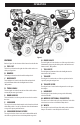
OPERATION A K L M C J D H I B D F N E M G Figure 1 FEATURES H. BRAKE LIGHTS A. FUEL CAP The brake lights are located on the rear of the cargo bed and are illuminated by depressing the brake pedal or when the hazard button is in the “ON” position. B. BUMPER The tail lights are illuminated when the headlight switch is turned to the “ON” position. Refer to Figure 1 for the location of the features described below.
OPERATION OCCUPANT PROTECTION STRUCTURE (OPS) & SEAT BELTS (NOT SHOWN) WARNING Always wear the seat belt when operating the utility vehicle. This utility vehicle is equipped with an Occupant Protection Structure (OPS) and seat belts. When used together they are effective in reducing crushing injuries to the operator and passenger in the event of an accidental rollover or tip-over. The safety provided by the OPS is minimized if the seat belt is not properly adjusted AND buckled.
OPERATION M. WINCH CONTROL C. HEADLIGHT/TAIL LIGHT SWITCH The headlight/tail light switch turns the headlights, instrument cluster lights and tail lights “ON” and “OFF.” The winch control releases cable on the winch (“OUT”) or pulls the cable in (“IN”). D. HORN N. SHIFT LEVER The horn activates the horn under the hood when depressed. The shift lever changes the gears of the utility vehicle between park (“P”), reverse (“R”), neutral (“N”), high (“H”) and low (“L”). E.
OPERATION OPERATION • Read the danger, warning and caution labels located on the vehicle. First 50 Hours How a new vehicle is handled and maintained determines the life of the vehicle. • To avoid the danger of exhaust fumes, do not operate the utility vehicle in closed buildings without proper ventilation.
OPERATION Stopping the Engine 1. After slowing the engine to idle, turn the key to the OFF position. 5. Release brake pedal and slowly apply pressure to the gas pedal. 2. Remove the key. 6. Release gas and apply brake pedal evenly and firmly to slow down or stop. Warming Up 2WD/4WD CAUTION CAUTION When traveling at road speed, use only 2WD. When driving on icy, wet, or loose surfaces, make sure the vehicle is correctly loaded to avoid skidding and loss of steering control.
OPERATION Raising & Lowering the Tailgate The front and rear axle differentials can be activated when the utility vehicle is stopped and the shift lever is in the NEUTRAL position. To activate either axle differential press the upper portion of the front/rear axle differential switch. To deactivate the axle differential press the lower portion of the front/rear axle differential switch. Both, one or neither of the differentials can be active.
OPERATION • Length and Width: Measure the size of your truck or trailer by taking width and length measurements at the floor level. Compare these measurements to the width and length of your utility vehicle to make sure it will fit comfortably. 3. Once unloaded, lower the cargo bed and securely latch it before operating the utility vehicle. Do not drive the utility vehicle with cargo bed in the raised position.
OPERATION LOADING THE UTILITY VEHICLE If your truck or trailer’s load capacity is sufficient to transport the utility vehicle and you obtain the proper loading ramps and equipment to safely secure the utility vehicle to the truck or trailer, the only thing left to do is load it. Here’s how to best accomplish this task: 5. Use tie-down straps or cables to secure the ramps to the trailer or truck, via the bumper (steel bumpers only) or trailer hitch safety chain loops.
Check brake hose & pipe Replace intake air line Check intake air line Check PCV Accumulator Replace radiator hose & clamp Check radiator hose & clamp Check brake light switch Adjust parking brake Every 50 hours Every 100 hours Every 150 hours Every 200 hours Every 300 hours Every 500 hours Every 3900 hours Every year Every 2 years Every 4 years Before performing any type of maintenance/service, disengage all controls and stop the engine.
PRE-START CHECKLIST • Check parking brake. Make sure the parking brake indicator light comes on when the parking brake is ON. • Inspect the instrument panel for broken gauges and warning lamps. • Check the headlights and turn signals. Replace if broken.
PRODUCT CARE MAINTENANCE a WARNING To avoid personal injury, be sure to check and service the vehicle on a flat surface with the engine off and the parking brake ON. If servicing under the cargo bed, be sure that the cargo bed is supported so that it can not inadvertently close. Do not touch muffler or exhaust pipes while they are hot; Otherwise, severe burns could result.
PRODUCT CARE Removing the Battery Access Panel Jacking Up the Utility Vehicle Unlock the battery access panel under the seat by rotating the lock knob, then lifting the battery access panel (Figure 13). WARNING To avoid personal injury, death, or vehicle damage do not work under the vehicle unless it is secured by safe stands or suitable blocking. 1. Jack up the front end of the utility vehicle on the front frame tube (a) only (Figure 16).
PRODUCT CARE 2. To check the oil level, remove the dipstick (a), wipe it clean, replace it without re-threading the dipstick, and pull it out again, check to see if the level is too low and add new oil to the full level on the dipstick (a) (Figure 20).for the location of dipstick. a a a Figure 18 If the door is not latching properly, the latches (a)can be adjusted.
PRODUCT CARE Checking & Adding Brake Fluid 2. Check to see that the coolant level is between the FULL (a) and LOW (b) marks of recovery tank (c) (Figure 22). CAUTION Never operate the vehicle if the brake fluid is below the minimum mark. Use only DOT3 from a sealed container. Other types of brake fluid may ruin synthetic resin or rubber installed in brake system components and may cause brake failure. Avoid contamination of the brake fluid, thoroughly clean around the filler cap before removing.
PRODUCT CARE 2. Loosen the lock nut (a) and then tighten the bolt (b) to adjust the parking brake. Turn the bolt until it touches, then back it off a 1/4-turn (Figure 26). If there is play in the parking brake handle there is a secondary adjustment that can be performed. 1. Look inside the driver’s side wheel well and locate the adjustment point. Slide back the rubber cover (a) on the adjustment nuts (b) (Figure 27). a a b b Figure 25 1. Release the parking brake. 2.
PRODUCT CARE Checking the Engine Start System PRE-LOAD SPRING ADJUSTER (B) The pre-load adjuster is located in the body of the shock and controls the height of the vehicle. It can be adjusted to accommodate for different load situations. WARNING Do not allow anyone near the vehicle while testing. If the vehicle does not pass the test, do not operate the vehicle. NOTE: This adjustment requires a spanner wrench to complete. A spanner wrench is included in the tool kit shipped with this utility vehicle. 1.
PRODUCT CARE Changing the Oil WARNING Be sure to stop the engine before replacing oil. Allow engine to cool down sufficiently, oil can be hot and can burn. 1. Park the vehicle on a flat surface and raise the cargo bed. 2. To drain the used oil, remove the drain plug at the bottom of the engine and completely drain the oil into an oil pan. 3. After draining, reinstall the drain plug. 4. Put a film of clean engine oil on the rubber seal of the new filter. 5.
PRODUCT CARE Changing the Brake Fluid 8. Fill with fresh water/antifreeze up to the “FULL” mark on the recovery tank (Figure 22 on page 22). See your authorized service dealer to have the brake fluid changed. 9. Start and operate the engine for a few minutes. Replacing Radiator Hose 10. Stop the engine and let cool. See your authorized service dealer to have the radiator hose changed. 11. Check coolant level of recovery tank and coolant if necessary. Replacing Fuel Hose 12.
PRODUCT CARE 9. The utility vehicle’s genuine long-life coolant has a service life of 2 years. Be sure to change the coolant every 2 years. 5. Top off the radiator and replace the radiator cap. Then lower the front of the utility vehicle off the jack. 10. Burp (remove air from) the coolant system as instructed in the Burping (Removing Air From) the Coolant System section.
PRODUCT CARE 5. Clean the paper element with a soft brush or low pressure air. Be careful not to damage the paper pleats during cleaning. 2. Remove the drain and allow the water to run out (a). Then replace the drain and the middle skid plate (Figure 41). 6. Inspect the inner filter for deposits or damage. 7. If either filter are excessively dirty or damaged, replace filters as a set. a 8. Re-install the primary air filter element. 9.
PRODUCT CARE 4. Check the fuel filter, if it is clogged by debris or contaminated with water, replace it. 2. A boost charge is only for emergencies, it will partially charge the battery as quickly as possible. 5. To remove the in-line fuel filter clamps (b), slide the clamps (b) away from the in-line fuel filter (a). Twist and pull the fuel lines off of the in-line fuel filter (a) (Figure 43). 3. When exchanging an old battery for a new one, use a battery of equal specification.
PRODUCT CARE Cleaning the Spark Arrestor & Muffler If you intend to store your vehicle for an extended period of time, follow the procedures outlined below. WARNING These procedures will ensure that the vehicle is ready to operate with minimum preparation when it is removed from storage. Before touching any part of the exhaust system, be sure that it has had sufficient time to cool. Always wear safety goggles and face mask.
PRODUCT CARE TROUBLESHOOTING WARNING Before performing any type of maintenance/service, disengage all controls and stop the engine. Wait until all moving parts have come to a complete stop. Disconnect spark plug wire and ground it against the engine to prevent unintended starting. Always wear safety glasses during operation or while performing any adjustments or repairs. This section addresses minor service issues.
PRODUCT CARE Problem Engine does not restart when warm Cause Remedy 1. Poor quality fuel 1. Refer to Service manual. Ensure the unit contains at least 1/4 tank of clean fuel. 2. Fuel tank vent plugged 2. Contact your local authorized dealer for service. 3. Dirt in fuel filter 3. Contact your local authorized dealer for service. 4. Damaged electrical harness 4. Contact your local authorized dealer for service. 1. Blown fuse 1. Visually and mechanically inspect all fuses.
PRODUCT CARE Problem Engine overheats Engine loses power Starter does not work Starter cranks slowly Cause Remedy 1. Cooling fan not turning 1. Listen or look for the radiator fan to turn on. The unit must be running, or the key switch in the run position. If the dash indicates the engine has over heated, immediately turn the unit off and then turn the key switch to the run position. If the fan does not turn on, check the fuses.
PRODUCT CARE Problem Battery light comes on when engine is running Vehicle will not move Cause Remedy 1. Weak or Low Battery. 1. Check Battery Voltage. 2. Loose electrical connections within the charging system. 2. Ensure all electrical connections are secure. 3. Excessive current draw from Accessories. 3. Contact your local authorized dealer for a current draw inspection. 1. Shift Lever not in gear. 1. Check the dash display to ensure the desired direction of travel is indicated. 2.
SPECIFICATIONS Make Specifications 1 cylinder, 4-cycle, gasoline, SOHC, liquid cooled Type Displacement cc 546CC for 550UTV 735CC for 750UTV Horsepower Kw (HP) 20.2 (27.1) for 550UTV 28.8 (38.6) for 750UTV Rated Revolution rpm 5500 rpm for 550UTV 6000 for 750UTV Low Idling Revolution rpm 1500 ±150 Fuel Capacity L (U.S. gal.) 28 (7.4) Oil Capacity L (U.S. quart) 2.1 (2.
SPECIFICATIONS Make Suspension Specifications Front Independent, Dual A-arm type Rear Independent, Dual A-arm type Max rolling weight (Towing capacity) kg (lbs.) 544 (1200) Payload capacity (Cargo Bed) kg (lbs.) 227 (500) Vehicle Curb Weight kg (lbs.) 748 (1646) Width mm (in.) 1170 (46.06) Length mm (in.) 900 (35.43) Depth mm (in.) 280 (11) Volume m3 (cu. ft.) 0.29 (10.24) Bed height (Unloaded) mm (in.) 810 (31.89) Cargo bed capacity (1 row/2 row) kg (lbs.
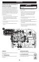
SPECIFICATIONS Fuse Box K1 K2 K3 F1 20A Fan motor fuse F2 5A Fan control system/Pump relay fuse K5 K4 F1 F2 F3 F4 F5 F6 F7 F8 F9 F10 F11 F12 F13 F14 F3 5A Winch controller fuse F4 5A The four-wheel drive differential control relay fuse OUT Spare Spare fuse fuse Flasher 20A 10A 5A 30A 10A 5A K1:MODEL: HFV11 12-H-R ( DG ) Fuel pump relay K2:MODEL: HFV11 12-H-R ( DG ) Neutral start relay K3:MODEL: HFV11 12-H-R ( DG ) Ignition switch relay K4:MODEL: HFV9 012-1ZR All-wheel-drive rel
Hisun Motors Corp., U.S.A. Emission Control System Warranty Statement YOUR WARRANTY RIGHTS AND OBLIGATIONS The U.S. Environmental Protection Agency and Hisun Motors Corp., U.S.A. (hereinafter “HISUN”) are pleased to explain the emission control system warranty on your Off-Road vehicle. New off-road motor vehicles must be designed, built and equipped to meet U.S. EPA Federal and California anti-smog standards.
Hisun Motors Corp., U.S.A. Limited Warranty on Emission Control System YOUR WARRANTY RIGHTS AND OBLIGATIONS Hisun Motors Corp., U.S.A. warrants that each new off-road vehicle: A. is designed, built and equipped so as to conform at the time of initial retail purchase with all applicable regulations of the United States Environmental Protection Agency, and B.
Hisun Motors Corp., U.S.A. Limited Warranty on Emission Control System B. No express emission control system warranty is given by HISUN except as specifically set forth herein. Any emission control system warranty implied by law, including any warranty of merchantability or fitness for a particular purpose, is limited to the express emission control system warranty terms stated in this warranty. The foregoing statements of warranty are exclusive and in lieu of all other remedies.