INTRODUCTION Welcome to the World of Cub Cadet Yanmar Tractor Thank you for purchasing our tractor product that has been designed and manufactured based on our state-of-the-art technology and rich expertise in developing and manufacturing tractor products. Handle your tractor correctly by following the instructions contained in this Operator’s Manual so that it provides you long years of reliable and faithful service. This manual constitutes an indispensable part of your Cub Cadet Yanmar tractor product.
TABLE OF CONTENTS 1. SAFETY PRECAUTIONS ................................................................................... 1-1 1. 2. 3. 4. About This Manual .................................................................................................................. 1-1 Safety Alert Symbol................................................................................................................. 1-2 Precautions Before Operating Your Tractor .......................................................
TABLE OF CONTENTS 3. Shutting Down the Engine....................................................................................................... 7-7 4. Restarting a stalled Engine ..................................................................................................... 7-8 8. OPERATING THE TRACTOR............................................................................. 8-1 1. Operating a New Tractor ........................................................................................
TABLE OF CONTENTS 2. Drawbar................................................................................................................................. 10-3 Maximum Allowable Load on the Drawbar ..........................................................................................................10-3 Adjusting the Drawbar .........................................................................................................................................10-3 3. Using the Safety Chain......
TABLE OF CONTENTS Checking the Fuel line .......................................................................................................................................14-10 Checking the Power Steering line .....................................................................................................................14-10 Checking the Seat Belt and Roll-Over Protective Structure (ROPS).................................................................
TABLE OF CONTENTS Checking the Fuel Injection Pump .....................................................................................................................14-33 10.General Maintenance .......................................................................................................... 14-34 Selecting the Rotational Direction of Front Tires ...............................................................................................14-34 Changing Wheel Spacing and Tread Width .....
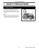
1. SAFETY PRECAUTIONS 1. SAFETY PRECAUTIONS 1. About This Manual This operator’s manual presents you messages that help you remain aware of potential hazards and possible machine damage in operating and servicing your machine. Carefully study all the information in it so that you can positively avoid personal injury and damaged properties.
1. SAFETY PRECAUTIONS 2. Safety Alert Symbol The safety alert symbol appear with most safety statements. It means attention, become alert, your safety is involved! Please read and strictly observe the message that follows the safety alert symbol. CAUTION Indicates a hazardous situation which, if not avoided, could result in minor or moderate injury. NOTICE Indicates a situation which can cause damage to the machine, personal property and/or the environment or cause the equipment to operate improperly.
1. SAFETY PRECAUTIONS 3. Precautions Before Operating Your Tractor your local Cub Cadet Yanmar dealer for technical assistance. 4. Always fasten the seat belt while operating the tractor with the Roll-Over Protective Structure (ROPS) up. Check the seat belt for any damage. Replace the damaged seat belt immediately. Contact your local Cub Cadet Yanmar dealer for technical assistance.
1. SAFETY PRECAUTIONS 14. Use the handholds and running board steps when getting on and off the tractor to help prevent accidental falls. Keep the running boards clear of mud and debris. 15. Only use the implements that satisfy the requirements in this manual or are approved by your Cub Cadet Yanmar dealer. (See “4. IMPLEMENT CAPACITIES”) 16. When using front or rear mounted implements, install an appropriate weight(s) to the front or rear of your tractor to prevent upsetting of the tractor.
1. SAFETY PRECAUTIONS 3. Considerations for Safety of Children 8. Avoid accidental contact with control pedals while the engine is running, as this can cause unexpected movement of the tractor. 9. Never leave a running machine unattended. Tragic accidents can occur if the operator is not alert to the presence of children. Children are often attracted to the machine. They do not understand the dangers. Never assume they will remain where you last saw them. 2. Working with Your Tractor 1.
1. SAFETY PRECAUTIONS 5. Operating Your Tractor on Slopes DO NOT: On a slope, the tractor is less stable and more prone to tip-over, possibly leading to serious injury or death. Remain very cautious when your tractor is on any slope. ●Do not mow near drop-offs, ditches or embankments. The mower could suddenly turn over if a wheel goes over the edge of a cliff or ditch, or if an edge caves in. WARNING ●Before approaching a slope, select an appropriate speed setting.
1. SAFETY PRECAUTIONS 6. Traveling on a Road 8. Avoid engaging differential lock while traveling on a road. It may cause you to lose control of the tractor. 9. While traveling on a road, do not suddenly turn the steering wheel. Such an action can lead to loss in the stability of the tractor, and can cause an extremely dangerous situation. 10. While on a road, do not attempt to operate an implement.
1. SAFETY PRECAUTIONS 8. Operating the Power Take Off (PTO) 3. Before installing or operating Power Take Off (PTO)-driven implement, carefully study the manufacturer’s operator’s manual and the safety decals on the implement. 4. When installing stationary Power Take Off (PTO)drive implements, be sure to engage the parking brake securely and securely place chocks in front and behind the rear wheels. Do not approach or access any rotating component. 1.
1. SAFETY PRECAUTIONS 11. Safe Practices for Servicing Your Tractor 10. Carefully loosen the radiator cap to the first stop, and allow excessive pressure to escape, and only then remove the radiator cap. If the tractor is equipped with a coolant reserve tank, add coolant or water to the reserve tank, not to the radiator (See “Checking the Cooling System”).
1. SAFETY PRECAUTIONS 19. Do not change the engine governor settings or overspeed the engine. Excessive engine speeds are dangerous. 20. Observe proper disposal laws and regulations. Prior to disposal, determine the proper method to dispose of waste from your local Environmental Protection Agency. Recycling centers are established to properly dispose of materials in an environmentally safe fashion. 21. Use proper containers when draining fluids.
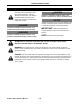
1. SAFETY PRECAUTIONS 12. Understanding the Tractor Safety Decals ■ Safety-Alert Symbol The tractor safety decals illustrated in this section are provided in critical areas on the tractor so that people including the operator can remain always aware of potential hazards. The tractor safety decals contain the words DANGER, WARNING and CAUTION together with the safety-alert symbol. DANGER and WARNING stand for the most serious hazards.
1. SAFETY PRECAUTIONS (A) CY1A8160-85170 (A) WARNING This structure's protective capability may be impaired by structural damage, overturn, or alteration. If any of these conditions occur, the structure must be replaced. (B) (B) CY1A8160-85180 WARNING Use retractable seat belt. A3013730 (A) P3013720 (B) (C) CY1A8160-65321 WARNING 1. Read Operator's Manual before operating this tractor. 2. Do not operate the machine without guards, shields, and safety devices in place and working. 3.
1. SAFETY PRECAUTIONS (D) CY1A8160-65310 (D) WARNING (E) TO AVOID INJURY: Before leaving or servicing machine, ●Stop engine. ●Set parking brake. ●Park on level ground. ●Lower all implements to the ground. ●Remove key. (E) CY1A8160-65350 WARNING TO AVOID INJURY OR DEATH FROM ROLLOVER: P3013728 ●Keep Rollover Protective Structure (ROPS) fully extended. ●Do not jump if machine tips. ●Use retractable seat belt. THERE IS NO OPERATOR PROTECTION WHEN THE ROPS IS IN THE FOLDED POSITION.
1. SAFETY PRECAUTIONS (H) CY1A8160-65300 DANGER TO AVOID INJURY OR DEATH: ●Do not start engine by shorting across starter terminals or bypassing safety start switch. ●Start engine only from seat with transmission and PTO OFF. (H) P3013739 (I-a) CY1A8160-51520 ( I-a ) DANGER/POISON (E) ●SHIELD EYES: EXPLOSIVE GASES CAN CAUSE BLINDNESS OR INJURY. ●NO SPARKS, FLAMES, SMOKING. ●SULFURIC ACID CAN CAUSE BLINDNESS OR SEVERE BURNS. ●FLUSH EYES IMMEDIATELY WITH WATER. SEEK MEDICAL HELP RIGHT AWAY.
1. SAFETY PRECAUTIONS (J) CY198220-65621 (J) WARNING AVOID INJURY FROM PTO: ●Keep all shields in place. ●Keep hands, feet and clothing away. ●Operate only with 540 RPM. P3013723 (J) P3013722 (K) CY124764-44810 (K) CAUTION 1. Adding of water is done through the sub-tank. 2. Before starting, make sure that water level is up to the "Full" mark. 3. If water level is low, remove the cap of the sub-tank and add water until the "Full" mark is reached.
2. SERVICING THE TRACTOR 2. SERVICING THE TRACTOR Your Cub Cadet Yanmar dealer wants to remain committed to the tractors our customers have purchased and intends to support our customers in fully developing the performance of their Cub Cadet Yanmar tractors. After carefully studying this manual, the customers themselves will be able to do a certain portion of the regular maintenance work.
3. SPECIFICATIONS 3. SPECIFICATIONS 1. Specifications Table Model Power Take Off (PTO) Power hp (kW) Ex2900 Ex3200 22.7 (17.0) 25.5 (19) Maker YANMAR Model 3TNV88 Type Direct Injection, Vertical, Water-Cooled, 4 Cycle Diesel Number of Cylinders Bore and Stroke Engine Total Displacement 3 in. (mm) 3.5×3.5 (88×90) cu. in. (L) 100.2 (1.642) Gross Power hp (kW) 28.7 (21.4) 31.5 (23.5) Net Power hp (kW) 27.4 (20.4) 29.6 (22.
3. SPECIFICATIONS Ag (R1) Tire Traveling System Turf (R3) Industrial (R4) Front 7-14 Rear 11.2-24 Front 25×8.50-14 Rear 13.6-16 Front 25×8.50-14 Rear 15-19.5 Clutch Dry Type Single Stage Steering Power Steering Transmission Hydrostatic Transmission, 3 Range Speeds Brake Wet Multi-Plates Minimum Turning Radius ft (m) 8.7 (2.7) Hydraulic Control System Hydraulic Unit Position Control Pump Capacity (main) US gal/min (L/min) Approximately 5.6 (21.
4. IMPLEMENT CAPACITIES 4. IMPLEMENT CAPACITIES The Cub Cadet Yanmar tractor has been carefully tested in the configuration equipped with implements sold or approved by Cub Cadet Yanmar and has proved to perform properly. Do not use any implement that has not been sold or recommended by a Cub Cadet Yanmar dealer, or that fails to satisfy the specified values given below. Never mount an implement that is not approved for the Cub Cadet Yanmar tractor.
4.
5. NAMES AND FUNCTIONS OF COMPONENTS 5. NAMES AND FUNCTIONS OF COMPONENTS 1.
5. NAMES AND FUNCTIONS OF COMPONENTS 2.
5. NAMES AND FUNCTIONS OF COMPONENTS 3. Instrument Panel, Switches and Hand Controls (1) (2) (3) 3013723 (7) (6) (5) (4) (4) Engine Oil Pressure Warning Light This light remains lit when the starter key switch is in the ON position and the engine is OFF. (1) Fuel Gauge This gauge indicates level of fuel in the fuel tank. (2) Tachometer This meter indicates the current engine speed in increments of 100 rpm.
5. NAMES AND FUNCTIONS OF COMPONENTS (8) (9) A3013703a (8) Headlight / Turn Signal Switch Use the blue lever to turn ON/OFF the headlights. Pushing this lever up will turn the headlights ON, and moving it down will turn the headlights OFF. The yellow lever is the turn signal switch. To signal a right turn, move the lever to right; to signal a left turn, move the lever to left. (a) (9) Hazard Lights Button Switch Depress the red button to turn the hazard lights ON.
6. PRE-OPERATION CHECK 6. PRE-OPERATION CHECK 1. Pre-Operation Check ●Check the tractor for damage, excessive wear, cracks, missing parts, exposed wiring and any other problems, including leaks. ●Check the joints and connections for looseness. ●Check that all the lights illuminate. ●Check that all the safety alert decals are in correct position. If any problem is detected, contact your local Cub Cadet Yanmar dealer, and correct the problem. NEVER operate the tractor when a problem has been indicated. 2.
7. OPERATING THE ENGINE 7. OPERATING THE ENGINE DANGER WARNING ALWAYS remain seated in the operator’s station when starting the engine or actuating the levers or controls. NEVER run or idle the engine in a confined area that is poorly ventilated or not ventilated at all. The engine emits carbon monoxide as that is colorless, odorless and can cause death.
7. OPERATING THE ENGINE 2. Engage the parking brake securely. ■ Engaging the Parking Brake (A) 1. Pull up the parking brake lever. 2. Fully depress the brake pedal. 3. Remove foot from the brake pedal and ensure that the brake has been fully locked. (A) Brake pedal (B) Parking brake lever (B) A3013703a 3. Set the range shift lever to the NEUTRAL position. (A) (A) Range shift lever (a) Neutral position (a) 3013703a 4. Set the Power Take Off (PTO) engagement lever to the OFF position.
7. OPERATING THE ENGINE 6. If the tractor has any implements that use the implement control valve, lower them to the ground (including the front-mounted one). (a) (A) Implement control lever (a) Lower the implement to the ground 3013703 7. Pull the throttle control lever by 1/3 to 1/2 stroke. (b) (A) Throttle control lever (a) To increase the engine speed, push the throttle control lever forward. (b) To decrease the engine speed, pull the throttle control lever back. (A) 3012724 8.
7. OPERATING THE ENGINE 9. Turn the starter key switch to the START position. (A) OFF position: The engine must not run. (B) ON position: When the starter key switch has been turned to this position, the engine oil pressure warning light and battery charge indicator light will illuminate. (C) START position: When the starter key switch is turned to this position, the starter starts running to turn the flywheel and the engine begins to run. Once the engine has started, release the starter key switch.
7. OPERATING THE ENGINE ■ Checking the Lights on the Instrument Panel 1. When the parking brake is in the locked state, the parking indicator light turns ON. 2. The engine oil pressure light turns ON. 3. The alternator / battery light turns ON. (A) Parking indicator light (B) Engine oil pressure warning light (C) Alternator / Battery charging light NOTE: ●The engine oil pressure light turns OFF within 5 seconds after the engine is started.
7. OPERATING THE ENGINE 2. Starting the Engine in Cold Weather Use the glow plug when the air temperature is 23°F (–5°C) or lower. 1. Move the key switch to the GLOW position (A). Hold the key switch in the GLOW position for no more than 20 seconds. 2. Move the key switch to the START position and start the engine. IMPORTANT: Avoid starter damage. ●NEVER operate the starter for more than 20 seconds. If the engine fails to start, wait for 2 minutes before attempting to start the engine again.
7. OPERATING THE ENGINE 3. Shutting Down the Engine 1. Remove foot from the forward and reverse drive pedals. 2. Run the engine at a lowest possible speed. 3. Depress the clutch pedal to disengage the clutch, and then depress the brake pedal. 4. After the tractor has completely stopped, disengage the Power Take Off (PTO), lower the implement (if installed) to the ground and then, engage the parking brake securely. 5. Run the engine at a lowest possible speed for at least 2 minutes. 6.
7. OPERATING THE ENGINE 4. Restarting a stalled Engine IMPORTANT: Avoid engine damage. ●If the engine stalls while operating under load, immediately restart the engine to prevent over-heating of the engine. 1. Turn the range shift lever to the NEUTRAL position. (A) (A) Range shift lever (a) Neutral position (a) 3013703a 2. Move the Power Take Off (PTO) engagement lever to the OFF position.
8. OPERATING THE TRACTOR 8. OPERATING THE TRACTOR DANGER ALWAYS use the drawbar to tow an implement. NEVER attach a load to the axle housing. WARNING Accident Hazard ALWAYS decrease tractor speed before turning, when traveling on a rough terrain or before stopping to prevent roll-over. ALWAYS remain alert to behaviors of children when operating the tractor because they are usually very curious about moving machines. Do not attempt to turn with the differential lock engaged.
8. OPERATING THE TRACTOR 1. Operating a New Tractor The service life of the tractor is governed by how adequately it is handled and maintained. Of course, any newly manufactured tractor has been tested; however, various parts must be broken in. Therefore, operate the tractor at low speeds for the first 50 operating hours, and avoid heavy work or operation before the various parts have been sufficiently run.
8. OPERATING THE TRACTOR 2. Raising and Lowering the Roll-Over Protective Structure (ROPS) WARNING Avoid injury: ●NEVER operate the tractor with the Roll-Over Protective Structure (ROPS) in the lowered (folded) position unless the tractor needs to be operated in a low clearance situation. Keep the retractable seat belt fastened while operating the tractor with the Roll-Over Protective Structure (ROPS) in the raised position.
8. OPERATING THE TRACTOR 2. Raising (Unfolding) the Roll-Over Protective Structure (ROPS) 1. Pull out the cotter pin from each of the insert pins on both sides of the Roll-Over Protective Structure (ROPS). (A) (B) (A) Cotter pin (B) Insert pin 2. Pull out the insert pins from both sides of the Roll-Over Protective Structure (ROPS). 3. Raise (unfold) the Roll-Over Protective Structure (ROPS). 4.
8. OPERATING THE TRACTOR 3. Operation of the Tractor CAUTION Avoid injury: ●Before starting or operating the tractor, always check the area around the tractor for bystanders and obstacles. Disengage the Power Take Off (PTO) and raise the implement. IMPORTANT: Avoid damage. ●To prevent damage to the transmission, stop the tractor completely before shifting the range shift lever. 1. Adjust the operator's position. ■ Adjusting the Operator's Seat 1. Sit on the seat. 2. Raise the seat adjustment lever. 3.
8. OPERATING THE TRACTOR ■ Fastening the Retractable Seat Belt WARNING Avoid injury: ●ALWAYS keep the retractable seat belt fastened while operating the tractor with the Roll-Over Protective Structure (ROPS) in the upright position. This will reduce the possibility of injury or death in the event of an accident such as an overturn or rollover.
8. OPERATING THE TRACTOR ■ Headlights Move the headlight lever up to turn OFF the headlights, and down to turn ON the headlights. (A) (A) Headlight lever ON OFF A2019004 ■ Hazard Lights Pushing the hazard lights button switch will cause the hazard lights to flash. (A) (A) Hazard lights button switch 3. Start the engine. Start the engine by referring to “7. OPERATING THE ENGINE”. A3013703a 4. Select travel speed.
8. OPERATING THE TRACTOR ■ 4-Wheel Drive Lever In the 4-wheel drive mode, all the four wheels are powered to obtain better traction on difficult-to-travel ground. The 4-wheel drive lever can be set to the ON or OFF position only when the tractor is at a standstill. (a) 2-wheel drive mode (b) 4-wheel drive mode (b) (a) IMPORTANT: Avoid damage. ●ALWAYS keep the 4-wheel drive lever in the OFF position when traveling on a paved surface.
8. OPERATING THE TRACTOR 6. Raise the implement. 1. Move the 3-point hitch control lever backward to raise the implements installed to the rear-and mid-mounts. 2. If the tractor has any implements that use the implement control valve, raise them using the implement control lever. (B) (A) (A) 3-point hitch control lever (B) Implement control lever 3013703a 7. Disengage the parking brake. 1. Depress the parking brake lever downward. NOTE: (A) ●Now, the parking brake lever incompletely lowers. (B) 2.
8. OPERATING THE TRACTOR ■ Drive Pedals The tractor accelerated speed depends on how far the drive pedal is pressed. (A) To move forward: depress the forward drive pedal. (B) To move backward: depress the reverse drive pedal. (A) (A) Forward drive pedal (B) Reverse drive pedal (B) IMPORTANT: ●When the drive pedal is released, the transmission will automatically return to NEUTRAL position. 10.Operate the steering wheel and travel to the intended destination. 11.Using the cruise control.
8. OPERATING THE TRACTOR ■ Engaging the Cruise Control 1. Depress the forward drive pedal until an intended travel speed is reached. 2. Lift up the cruise control lever to engage the cruise control feature. 3. Remove the foot from the forward drive pedal. 4. Remove hand from the cruise control lever. (B) (A) (A) Forward drive pedal (B) Cruise control lever A3013703 ■ Disengaging the Cruise Control 1. Depress the forward drive pedal. 2.
8. OPERATING THE TRACTOR 4. Stopping Travel of the Tractor WARNING Avoid injury: ●Slow down before making a turn. 1. Release the forward / reverse drive pedals. 2. Idle the engine. 3. Depress the clutch pedal to disengage the clutch and then depress the brake pedal. 4. After the tractor has completely stopped, disengage the Power Take Off (PTO). 5. Turn the starter key switch to the OFF position. 6. Remove the starter key switch.
8. OPERATING THE TRACTOR 5. Parking the Tractor ■ Engaging the Parking Brake CAUTION Avoid injury: ●ALWAYS engage the parking brake securely before leaving the tractor unattended. 1. Disengage the Power Take Off (PTO), lower the implement to the ground, shift all the levers to their neutral positions, engage the parking brake securely, shut down the engine and remove the key from the starter switch. 2. Before leaving your tractor, be fully sure that your tractor is at a standstill. 3.
8. OPERATING THE TRACTOR 6. Safe Practices for Operation 1. Differential Lock (A) Differential lock foot pedal WARNING Avoid injury. To prevent tipping of the tractor: ●Do not attempt to turn with the differential lock engaged. ●Do not engage the differential lock while the tractor is traveling at a high speed. The differential lock is actuated to provide greater traction when rear wheels begin to slip.
8. OPERATING THE TRACTOR 2. Safely Driving the Tractor on Roads WARNING Avoid injury. Be cautious when driving the tractor at a transport speed: ●We recommend that the user / operator use the turn signal / hazard lights when traveling on public roads. Before operating the tractor on a public roadway, be aware of relevant state or local regulations in effect. An implement safety lighting kit is available from your local Cub Cadet Yanmar dealer.
8. OPERATING THE TRACTOR ●Strictly observe all the currently effective local traffic and safety laws and regulations. ●ALWAYS travel at a speed that allows the tractor to remain controlled and stable. ●Avoid engaging differential lock while traveling on a road. Your tractor can lose control. ●While traveling on a road, do not suddenly turn the steering wheel. Such an action can lead to loss in the stability of the tractor, and can cause an extremely dangerous situation.
8. OPERATING THE TRACTOR 4. Transporting the Tractor on a Trailer WARNING Avoid injury: ●Exercise extreme care when loading or unloading the tractor to or from a trailer or truck. ●Close the fuel shut-off valve. NOTE: ●Use a heavy-duty trailer to transport the tractor. 1. 2. 3. 4. 5. 6. 7. Drive the tractor forward onto the trailer. Lower any implement onto the trailer deck. Engage the parking brake securely. Turn off the engine. Remove the key from the starter key switch. Close the fuel shut-off valve.
8. OPERATING THE TRACTOR WARNING If the clutch pedal is depressed ●Before approaching a slope, select an appropriate speed setting. NEVER shift on a slope. Otherwise, the tractor may suddenly go downhill and go out of control. Be sure to travel at a lower speed on a slope. ●On a slope, NEVER move the range shift lever to the NEUTRAL position. ●On a slope, NEVER step on the clutch pedal. Otherwise, the tractor may suddenly go downhill and go out of control.
8. OPERATING THE TRACTOR 1. Before approaching a slope, select a lower gear setting. (A) (A) Range shift lever (a) Shift to a lower speed 1 2 2. ALWAYS travel slowly on a slope. 3. Drive the tractor according to the type of a slope, as instructed below: (a) 3013703c ■ Uphill / Downhill Start slowly. Ensure that the transmission is in a slow setting. Run the engine at a lower speed. ■ Steep Downhill To be able to apply the engine brake, turn the range shift lever to the lowest speed range.
9. POWER TAKE OFF (PTO) 9. POWER TAKE OFF (PTO) WARNING ALWAYS ensure all moving components have stopped rotating before connecting, disconnecting, adjusting, cleaning or servicing any Power Take Off (PTO)-driven implement. ALWAYS follow the Power Take Off (PTO) -driven implement operation manuals and safety decals and instructions before installing or operating any Power Take Off (PTO) -driven implements. ALWAYS ensure the Power Take Off (PTO) shaft cover is installed.
9. POWER TAKE OFF (PTO) ■ Engaging the Power Take Off (PTO) (when the operator is seated on the operator's seat) NOTE: ●When either the Mid-Power Take Off (PTO) engagement lever or Rear Power Take Off (PTO) engagement lever is in the engaged position, the engine will not start. This situation is considered normal operation.
9. POWER TAKE OFF (PTO) ■ Disengaging the Power Take Off (PTO) (when the operator is seated on the operator's seat) 1. Run the engine at a low speed. 2. Fully depress the clutch pedal to disengage the clutch. 3. Push the selected Power Take Off (PTO) engagement lever downward, then horizontally and pull the lever slightly upward to the disengaged position. (A) (B) (A) Rear Power Take Off (PTO) engagement lever (B) Mid-Power Take Off (PTO) engagement lever 4. Release the clutch pedal. 3013711 2.
9. POWER TAKE OFF (PTO) 3. Using the Power Take Off (PTO) while the Tractor is Parked (when the operator is not seated on the operator's seat) Follow the instructions below when using the Power Take Off (PTO) when the tractor is in the parked state (for example, for pump, for post hole digger). In this mode, only the Rear Power Take Off (PTO) can be operated, the Mid-Power Take Off (PTO) is inoperable. CAUTION ●Engage the parking brake securely, and keep the transmission in the neutral position.
9. POWER TAKE OFF (PTO) 4. Move each Power Take Off (PTO) engagement lever to the OFF position. (A) (A) Rear Power Take Off (PTO) engagement lever (B) Mid-Power Take Off (PTO) engagement lever (option) (a) OFF position (a) (B) (a) 3013711b (C) Switch plunger (Seat safety switch) (C) P3013702 5. Sit on the operator’s seat. 6. Start the engine. 7. Fully depress the clutch pedal and pull the Rear Power Take Off (PTO) engagement lever to the engaged position.
10. 3-POINT HITCH AND DRAWBAR 10. 3-POINT HITCH AND DRAWBAR WARNING ALWAYS use implements designed for a 3-point hitch. NEVER use unapproved implements with the 3-point hitch. Contact your authorized Cub Cadet Yanmar dealer for assistance. ALWAYS install an appropriate counterbalance to the front of the tractor, if necessary, when using a 3point hitch-mounted implement. During transportation, put the 3-point hitch control lever in its raised position and lock it with the position stop knob.
10. 3-POINT HITCH AND DRAWBAR 2. Using the 3-Point Hitch ■ Adjusting the Right Lift Link 1. 2. 3. 4. Lower the rear-mounted implement. Safely stop the machine. Loosen the locknut. Turn the turnbuckle to adjust the length of lift link until the implement mounted to the 3-point hitch is level. 5. Retighten the locknut. (A) (B) (A) Locknut (B) Turnbuckle 3013733 ■ Top Link Adjust the angle of the attached implement by lengthening or shortening the top link.
10. 3-POINT HITCH AND DRAWBAR 2. Drawbar The drawbar has two adjusting holes that allow the user to adjust the drawbar length. WARNING Avoid injury: ●Only hitch a towed load to the drawbar to avoid tipover. NEVER use the safety chain to tow a load. ■ Maximum Allowable Load on the Drawbar The drawbar may be overloaded when it is equipped with a very heavy unit such as a single-axle trailer.
10. 3-POINT HITCH AND DRAWBAR 3. Using the Safety Chain WARNING Avoid injury: ●Only hitch a towed load to the drawbar to avoid tip over. NEVER use the safety chain to tow a load. IMPORTANT: Avoid damage. ●ALWAYS secure the towed implement to the drawbar. The safety chain is intended to control the towed implement if it is accidentally disconnected from the drawbar. ●ALWAYS use a chain whose strength is rated greater than the gross weight of the towed implement.
11. HYDRAULIC SYSTEM 11. HYDRAULIC SYSTEM WARNING ALWAYS fully release the internal hydraulic pressure before disconnecting a hydraulic line. ALWAYS ensure that all connections are tight and all the hydraulic lines, pipes and hoses are free from wear or damage. 1. 3-Point Hitch Control System IMPORTANT: ●NEVER operate the 3-point hitch control lever before the engine has been sufficiently warmed up.
11. HYDRAULIC SYSTEM ■ Hydraulic Flow Control / Stop Knob WARNING ●Lowering the 3-point hitch too fast can lead to accident or failure. ●Adjust the hydraulic flow control / stop knob so that the time for lowering the implement from the highest position to the lowest position becomes 2 seconds or longer. ●While on a road, do not attempt to operate an implement. During transportation, put the 3-point hitch control lever in its raised position and lock it with the position stop knob.
11. HYDRAULIC SYSTEM 2. Controlling the Implement Control Valve ■ Implement Control Lever (A) Implement control lever (A) These couplers are used in pairs of 1 and 2, and 3 and 4.
11. HYDRAULIC SYSTEM 1. Using the Hydraulic Lock Lever Use the hydraulic lock lever to adjust the shift direction of the implement control lever in accordance with particular operating conditions or situations. (A) (A) Hydraulic lock lever (B) Shift pattern decal (1) (1) To limit the implement control lever to the right-left movement: Pull the lock lever outward (rightward), and then fully rearward as shown on the attached shift pattern.
11. HYDRAULIC SYSTEM DANGER Avoid injury: ●Escaping high pressure oil can penetrate the skin and cause severe injury. Avoid this hazard by relieving pressure prior to connection of hydraulic or other high pressure lines. Retighten all the connections before applying pressure. ●Use a piece of cardboard to detect leaks. Protect hands and body against high pressure fluids. ●If an accident should occur, immediately seek medical attention.
12. TIRES, WHEELS AND BALLAST 12. TIRES, WHEELS AND BALLAST ALWAYS keep the tractor securely supported while changing the wheels or adjusting the wheel tread width. WARNING NEVER attempt to mount a tire on a rim. Contact a reputable tire repair facility. ALWAYS keep the wheel bolts tightened to the specified torque. ALWAYS keep the tires inflated to the correct pressure. NEVER exceed the recommended tire pressure specified in this Operator’s Manual. 1.
12. TIRES, WHEELS AND BALLAST Tire size Tire air pressure 25X8.50-14(R4)(Industrial),6PR 50 psi (3.5 kgf/cm2) Front 25X8.50-14(R3)(Turf),4PR 22 psi (1.5 kgf/cm2) 7-14 (R1)(Agricultural),6PR 36 psi (2.5 kgf/cm2) 15-19.5 (R4) (Industrial),6PR 30 psi (2.1 kgf/cm2) Rear 13.6-16(R3) (Turf),4PR 11.2-24 (R1) (Agricultural),4PR 14 psi (1.0 kgf/cm2) 18 psi (1.3 kgf/cm2) 2. Wheel Adjustment Each tire size has specific adjustment settings that must not be changed.
12. TIRES, WHEELS AND BALLAST ■ Tread Centerline Width Tire Standard Setting Rear Front – 41.8 in. (1061mm) 38.9 in. (987mm) Wide 44.8 in. (1138mm) – Extra Wide 49.3 in. (1253mm) – 40.2 in. (1020mm) 38.4 in. (975mm) R1 R3 R4 43.9 in. (1114mm) 987 975 974 TIRE:25X8.50-14 R4 38.3 in. (974mm) 168 215 268 TIRE:25X8.50-14 R3 TIRE:7-14 R1 3013718 Wide and extra wide are achieved by changing the method of assembling the rims and the disk.
12. TIRES, WHEELS AND BALLAST 3. Ballast ■ Front Ballast To improve stability and traction, add ballast as needed. Heavy pulling and rear-mounted implements can cause the front wheels to lift. To cope with this situation, add ballast so that reliable steering control is maintained and tip-over of the tractor is prevented. Remove the ballast when no longer necessary. Front End Weights (option) The front end weights can be installed on the bumper.
12. TIRES, WHEELS AND BALLAST ■ Maximum Weight Usually, five 44 lb (20 kg) weights can be installed on the tractor. If the extension is used, four additional 44 lb (20 kg) weights can be installed. In other words, a total of nine 44 lb (20 kg) weights can be installed on the tractor for an additional total weight of 396 lb (180 kg). For the information about the extension and weights being installed, contact your local Cub Cadet Yanmar dealer.
13. MAINTENANCE 13. MAINTENANCE ●For the checkpoints (✔) listed below, check and service at the intervals indicated in the table. ●For the inspection and maintenance procedures, see “14. PERIODIC SERVICE”. 1.
13.
13. MAINTENANCE 3. Replacement Parts 1. Technical Document [U.S.A. and Canada] When wanting to obtain a copy of Parts Catalog or Technical Manual for your tractor, contact your local Cub Cadet Yanmar dealer. 2. Parts We recommend the use of the Cub Cadet Yanmar authentic parts and lubricants that are available from your local Cub Cadet Yanmar dealer. When ordering a part, tell your local dealer the machine serial number and engine serial number for your tractor.
14. PERIODIC SERVICE 14. PERIODIC SERVICE WARNING Explosion Hazard ALWAYS allow the tractor to fully cool down before accessing the engine, muffler, radiator or other hot components. NEVER smoke around the battery or during refueling. Keep sparks or open flames away from the battery and fuel tank. The battery emits hydrogen and oxygen during recharging and can pose a serious hazard.
14. PERIODIC SERVICE 1. Opening / Closing the Hood and Side Panels 1. Opening / Closing the Hood CAUTION ●Do not open the hood while the engine is running. ●Do not touch the hot muffler or exhaust pipe. ■ Opening the Hood 1. Pull the hood release lever upward. The hood lock will be released. (A) (A) Hood release lever P3013711 2. Lift up the hood with both hands. The hood support will automatically lock when the hood is fully raised.
14. PERIODIC SERVICE ■ Closing the Hood 1. Lift up the hood slightly, grasp the grip at the middle of the hood support and pull forward to unlock the hood support. (A) (B) (A) Hood support (B) Grip 2. Lower the hood and firmly press downward on the upper front portion of the hood until the hood latch locks the hood in the closed position. 3. Attempt to lift the hood to make sure the hood latch has locked the hood in the closed position.
14. PERIODIC SERVICE 2. Daily Checks ■ Checking the Engine Oil Level IMPORTANT: Avoid damage. ●ALWAYS check the oil level daily. If the oil level is low, a serious engine problem can occur. ●ALWAYS check the oil level before operation. ●ALWAYS check the oil level when the engine is cold and not running. ●ALWAYS maintain the oil level between the lower and the upper marks. ●ALWAYS shut the engine down and allow to cool before adding the engine oil.
14. PERIODIC SERVICE ■ Inspecting the Transmission Oil Level 1. Park the tractor safely. Allow the tractor to cool off for at least 1 hour. (B) IMPORTANT: Avoid damage. ●Prevent dirt and other contaminants from entering the transmission. Clean the area around the dipstick before removing it. ●NEVER overfill the transmission. 2. Remove the dipstick. 3. Read the oil level on the dipstick. The oil level should be between the high and low levels on the dipstick. (A) 3013705 4.
14. PERIODIC SERVICE Specified Torque Bolt fixing the disk to the axle Front wheel 127-141 ft•lb (172-191 N•m) Rear wheel 123-151 ft•lb (167-205 N•m) Bolt fixing the rim to Rear wheel the disk (Only R1 tire) 146-205 ft•lb (198-278 N•m) (A) Rim (B) Axle (C) Bolt fixing the rim to the disk (Only R1 tire) (D) Bolt fixing the disk to the axle (E) Disk Front wheel Rear wheel (A) (B) (C) (B) (E) (D) (E) (D) B3013701 ■ Checking and Adjusting the Brake Adjust the play of the brake pedal to 1.
14. PERIODIC SERVICE ■ Checking and Adjusting the Clutch 1. Stop the tractor, and chock the tires. 2. Shut down the engine, and remove the starter key switch. 3. Engage the parking brake securely and check that the parking brake is locked. 4. Lightly step on the clutch pedal to check that the play at the end of clutch pedal falls in a range of 0.59 to 0.98 in. (15 to 25 mm). 5. If the play needs to be adjusted, loosen the nut on the turnbuckle of the clutch rod.
14. PERIODIC SERVICE ■ Checking the Tire Air Pressure Adjust the front and rear tires to the standard pressure. Check the tires for fissures and any other damages. (a) Too high (b) Standard (c) Too low Tire pressures Tire size (a) Tire air pressure Front 25X8.50-14(R4) (Industrial),6PR 50 psi (3.5 kgf/cm2) 25X8.50-14(R3) (Turf),4PR 22 psi (1.5 kgf/cm2) 7-14 (R1) (Agricultural),6PR 36 psi (2.5 kgf/cm2) Rear 15-19.5 (R4) (Industrial),6PR 30 psi (2.1 kgf/cm2) 13.6-16(R3) (Turf),4PR 14 psi (1.
14. PERIODIC SERVICE ■ Cleaning the Radiator Cooling Screen, Cooling Fins and Oil Cooler Pipe CAUTION Avoid injury. Compressed air can cause debris and dirt to powerfully fly a long distance: ●NEVER allow bystanders near the tractor. ●When using compressed air for cleaning, ALWAYS wear protective goggles. ●Reduce compressed air pressure to 30 psi (210 kPa). (A) IMPORTANT: Avoid damage.
14. PERIODIC SERVICE ■ Cleaning the Grille and Side Screens IMPORTANT: Avoid damage. ●Clean the grille and side panel screens to prevent the engine from overheating and ensure adequate air inflow. (A) 1. Check the grille and both side panel screens for dirt, grass chippings and debris. 2. Clean the grille and side screens with a brush or cloth.
14. PERIODIC SERVICE ■ Checking the Cooling System CAUTION Avoid injury. ●ALWAYS allow radiator to cool before removing the radiator cap. The radiator will be hot and can cause burns. When the radiator cap is removed, pressure build-up in the cooling system can cause the coolant to spray out explosively. ●ALWAYS shut the engine down and allow it to cool. ●NEVER remove the radiator cap before the radiator and the engine are sufficiently cool such that they can be touched with bare hands.
14. PERIODIC SERVICE ■ Refilling the Fuel Tank IMPORTANT: Avoid damage. ●NEVER use a galvanized container to store fuel. Diesel fuel in a galvanized container reacts with the zinc coating in the container to generate zinc flakes. If the fuel contains water, a zinc gel will also occur. The zinc gel and flakes will quickly clog the fuel filter and damage the fuel injection nozzle and fuel pump. In cold climate, use Grade No. 1-D diesel fuel, and in warm climate, use Grade No. 2-D diesel fuel.
14. PERIODIC SERVICE 1. Park the tractor safely. 2. Allow the engine to cool off for several minutes before refueling. 3. Remove the fuel tank cap. 4. Fill the tank with fresh fuel to the bottom of filler neck. IMPORTANT: (A) (B) ●NEVER overfill the fuel tank. 5. Reinstall the fuel tank cap.
14. PERIODIC SERVICE 1. Range Shift Lever Neutral Switch 1. Sit on the operator’s seat. 2. Disengage the Rear Power Take Off (PTO) engagement lever (OFF position). If the machine has the Mid-Power Take Off (PTO) engagement lever, also disengage it. 3. Bring the range shift lever into the 1st, 2nd or 3rd speed setting. 4. Turn the starter key switch to the START position. 5. Check that the starter motor does not start. 6. Turn the range shift lever to the NEUTRAL position and check that engine starts.
14. PERIODIC SERVICE 3. Rear Power Take Off (PTO) Engagement Lever Switch 1. Sit on the operator’s seat. 2. If the machine has the Mid-Power Take Off (PTO) engagement lever, disengage it (OFF position). 3. Engage the Rear Power Take Off (PTO) engagement lever (ON position). 4. Move the range shift lever into the NEUTRAL position. 5. Turn the starter key switch to the START position. 6. Check that the starter motor does not start. 7.
14. PERIODIC SERVICE 5. Checking the Operation of the Seat Safety Switch 1. Move the range shift lever into the NEUTRAL position. 2. Disengage the Rear Power Take Off (PTO) engagement lever (OFF position). If the machine has the Mid-Power Take Off (PTO) engagement lever, disengage it. 3. Sit on the operator's seat. 4. Turn the starter key switch to the START position. 5. Check that the engine starts. 6. Remove all weights from the operator seat. 7.
14. PERIODIC SERVICE 4. Every 50 Hours ■ Checking the Front Axle Oil Level IMPORTANT: Avoid damage. ●Before checking the oil level, allow the oil to settle for 1 hour so that the current oil level can be accurately read on the dipstick. Recheck the oil level after operating the tractor for several hours. 1. Park the tractor safely. 2. Allow the tractor to cool off for at least 1 hour and the oil to settle. (A) IMPORTANT: Avoid damage. ●Dirt and debris in the oil may damage the transaxle.
14. PERIODIC SERVICE 1. Lubricating Grease Fittings on the Tractor [Extremely wet or muddy conditions] Lubricate the grease fittings once every 10 operating hours or once a day. [All other conditions] Lubricate the grease fittings once every 50 operating hours. (A) Right tie rod end (A) 3013707 (B) Left tie rod end (B) A3013719 (C) Axle pivot pin (C) A3013718 NOTE: ●The link grease fittings are located below the foot platform on the tractor.
14. PERIODIC SERVICE 2. Lubricating the Hydraulic Implement Control Valve Linkage (A) Lubricate the implement control valve linkage Lubricate the implement control valve linkage with Cub Cadet GEAR LUBE. (A) P3013706 3. Lubricating the Seat Slide Rails 1. Pivot the operator's seat forward. 2. Lubricate the seat slide rails with SUPER LUBE lubricant. 3. Lower the operator's seat. (A) (A) Seat slide rails P3013702 4.
14. PERIODIC SERVICE ■ Servicing the Fan and Alternator Belt WARNING Be careful to avoid injury: ●Fingers or loose clothing can be entangled with rotating parts. Before servicing, shut down the engine and allow all the moving parts to stop completely. 1. Checking the Belt Tension 1. 2. 3. 4. Park the tractor safely. Raise the hood. Remove the side panel from the left side of the engine. With a thumb, gently apply pressure to the midpoint of the belt between the pulleys.
14. PERIODIC SERVICE 8. Remove the belt from the alternator sheave, fan sheave and crankshaft sheave. 9. Route the defective belt over the fan, and then remove it. 10. Install a new belt over the fan and onto the sheaves. 11. Exert an outward pressure to the alternator housing to attain the correct tension. 12. Retighten the mounting bolt, mounting nut and adjusting bolt, in this order. 13. Check the belt tension. Adjust as necessary. 14. Reconnect the black negative (–) cable to the battery. 15.
14. PERIODIC SERVICE 5. Every 100 Hours ■ Servicing the Air Filter Element CAUTION Be careful to avoid injury: ●Touching hot surfaces can lead to skin burn. If the engine has been running, the engine and its components will remain hot. Before servicing, allow the engine to cool off. IMPORTANT: Avoid injury. A damaged filter element may fail to catch dirt and dust, and contaminants can enter the engine: ●NEVER wash the paper element. IMPORTANT: Avoid damage.
14. PERIODIC SERVICE 8. Reinstall the air cleaner element. If necessary, remove and discard the old primary element, and replace with a new primary filter element. 9. Reinstall the air cleaner canister cover. Make sure that the rubber dust unloading valve points downward. 10. For correct installation, follow the instruction molded onto the canister cover. 11. Hook the two latch hooks onto the air cleaner canister. 12. Lower the canister. 13.
14. PERIODIC SERVICE ■ Cleaning the Fuel / Water Separator and Replacing the Fuel Filter WARNING Avoid injury: ●Remember that vapor from diesel fuel is explosive and flammable. ●NEVER smoke while handling the fuel. ●Keep the fuel away from open flames or sparks. ●Before servicing, shut down the engine. ●Before servicing, allow the engine to cool off. ●Work in a well-ventilated area. ●Immediately wipe away spilled fuel. NOTE: ● Change the fuel filter if the fuel tank has been run dry. 1.
14. PERIODIC SERVICE 6. Every 200 Hours ■ Engine Oil Use an oil of the viscosity appropriate for the air temperature range expected until the next oil change interval. The following oils are recommended: Engine crankcase Capacities Lubricants API Service Classifications Approximately 1.1 US gal CF or higher (4.0 L) SAE 10W-30 or SAE 10W-40 ■ Changing the Engine Oil and Filter 3013738 IMPORTANT: Avoid damage.
14. PERIODIC SERVICE 10. Apply a small amount of clean engine oil onto the gasket of the new filter. 11. Install a new replacement oil filter by turning it clockwise until the gasket is seated against the filter base. Then turn the filter an additional one half turn. 12. Reinstall the drain plug. Do not over-tighten it. 13. Remove the oil fill cap. 14. Add approximately 1.1 US gal (4.0 L) of the engine oil. 15. Reinstall the oil fill cap. 16. Start and idle the engine to check for any leaks. 17.
14. PERIODIC SERVICE 7. Every 300 Hours ■ Transmission Oil IMPORTANT: ●Make sure to use Cub Cadet Hydraulic / Transmission Fluid for transmission oil. Transmission Capacities Lubricants Approximately 5.4 US gal Cub Cadet Hydraulic / (20.3 L) Transmission Fluid ■ Changing the Transmission Oil and Filter, Cleaning the Transmission Oil Strainer WARNING Avoid injury: ●When draining away the transmission oil that is still hot, stay clear of the hot transmission oil and other components to avoid burn.
14. PERIODIC SERVICE 4. Turn the transmission oil filter with the filter wrench to remove. 5. Install a new transmission oil filter and turn clockwise by hand. Tighten the filter with the filter wrench to a torque of 28.9 lb•ft (4kgf•m). (C) Transmission oil filter 35 micron (D) Transmission oil filter 10 micron NOTE: ●After hand-tightening, only tighten by 2/3 turn with the filter wrench. (C) P3013747 (D) 3013766 6.
14. PERIODIC SERVICE 8. Every 500 Hours ■ Front Axle Case Oil Front Axle Case Oil IMPORTANT: ●Make sure to use Cub Cadet GEAR LUBE or SAE 80W-90 gear oil for front axle case oil. Capacities Lubricants Approximately 1.2 US gal Cub Cadet GEAR LUBE (4.7 L) or SAE 80W-90 gear oil ■ Changing the Front Axle Case Oil 1. Operate the tractor to warm up the front axle oil. 2. Park the tractor safely. 3. Place a drain pan below the differential drain plug. (A) NOTE: ●The front axle contains approximately 1.
14. PERIODIC SERVICE ■ Replacing the Fuel Filter WARNING Avoid injury: ●Remember that vapor from diesel fuel is explosive and flammable. ●NEVER smoke while handling the fuel. ●Keep the fuel away from open flames or sparks. ●Before servicing, shut down the engine. ●Before servicing, allow the engine to cool off. ●Work in a well-ventilated area. ●Immediately wipe away spilled fuel. Replace the fuel filter every 500 hours.
14. PERIODIC SERVICE 9. Every 1000 Hours ■ Servicing the Cooling System CAUTION Avoid injury. ●ALWAYS allow radiator to cool before removing the radiator cap. The radiator will be hot and can cause burns. When the radiator cap is removed, pressure build-up in the cooling system can cause the coolant to spray out explosively. ●ALWAYS shut the engine down and allow it to cool.
14. PERIODIC SERVICE 2. Flushing the Cooling System 1. Fill the cooling system with water and common flushing / cooling liquid. Follow the manufacturer’s instructions. 2. Reinstall and retighten the radiator cap. 3. Start and run the engine until it reaches the operating temperature. CAUTION Avoid injury: ●The engine and coolant can be hot. Avoid contact with skin to prevent severe burns. ALWAYS wear safety glasses when draining the cooling system. 4. Shut down the engine. 5.
14. PERIODIC SERVICE ■ Recommended Engine Coolant CAUTION Avoid injury: ●Fluids released under pressure from the cooling system can cause severe burns. Pressure build-up in the cooling system can, when the radiator cap is removed, cause the coolant to gush out explosively. ●Shut down the engine and allow it to cool off. ●Do not remove the radiator cap before the radiator and the engine are sufficiently cool such that they can be touched with bare hands.
14. PERIODIC SERVICE 10. General Maintenance NOTE: ●Replace the air cleaner element at least once a year. ●Replace the cooler flushing liquid at least once a year. ●Replace the radiator hoses at least once every two years. ●Replace the fuel hoses at least once every two years. ●Replace the air intake hose at least once every two years. ●Replace the PST hose at least once every two years.
15. SERVICING THE ELECTRICAL SYSTEM 15. SERVICING THE ELECTRICAL SYSTEM WARNING ●To avoid personal injury, do as follows: ●Read the “1. SAFETY PRECAUTIONS” at the head of this manual. ●Read the danger, warning and caution statements on the safety alert decals on the tractor. ●To avoid possible poisoning from exhaust fume, do not operate the engine in an enclosed place that lacks adequate ventilation. ●NEVER start the engine while standing on the ground.
15. SERVICING THE ELECTRICAL SYSTEM ■ Servicing the Battery Safely WARNING Avoid personal injury. The battery electrolyte contains sulfuric acid, which is poisonous and can cause serious burn: ●Wear protective goggles and gloves. ●NEVER expose skin. ●If electrolyte is accidentally swallowed, immediately seek medical attention. ●If the electrolyte has entered eyes, immediately flush with running water for 15-30 minutes and seek medical attention.
15. SERVICING THE ELECTRICAL SYSTEM ■ Inspecting the Battery The battery used on your tractor is a maintenance-free design. Do not add electrolyte or recharge it. When the engine is off, measure the voltage on the battery across the positive and negative posts. If the reading is 11 V or lower, replace the battery with a new one.
15. SERVICING THE ELECTRICAL SYSTEM 2. Installing the Battery 1. Install the battery onto the tractor. 2. Inspect the battery vent to be sure that the vent holes are open. 3. Connect the positive (+) cable to the battery first, and then the negative (–) cable. 4. Apply petroleum jelly to the battery terminals to protect them against corrosion. 5. Install the battery hold-down assembly. Avoid overtightening. 6. Lower the hood. ■ Cleaning the Battery and Terminals 1.
15. SERVICING THE ELECTRICAL SYSTEM ■ Using a Booster Battery WARNING Avoid personal injury: ●NEVER attempt to jump-start a frozen battery. Warm it to 60°F (16°C). ●NEVER connect the negative (–) booster cable to the negative (–) terminal of the discharged battery. Connect to an appropriate grounding point other than the discharged battery.
15. SERVICING THE ELECTRICAL SYSTEM 2. Fuses IMPORTANT: Avoid damage. ●Use of a fuse other than a correctly rated one may cause damage to the electrical system. Replace the blown fuse with a new fuse of the same amperage rating. ■ Replacing the Accessory Fuses 1. 2. 3. 4. 5. 6. 7. 8. Park the tractor safely. Raise the hood. Grip both ends of the fuse holder cover and remove. Locate the fuses by referring to the diagram at the right. Remove the blown fuse from its socket.
15. SERVICING THE ELECTRICAL SYSTEM 3. Bulb ■ Replacing the Headlight Bulb IMPORTANT: Avoid damage. ●NEVER touch the headlight bulb with bare fingers, otherwise, the bulb may fail prematurely. When inspecting or replacing the bulb, use gloves or a piece of cloth to handle the bulb. 1. 2. 3. 4. 5. Park your tractor safely. Stop the engine and remove the key. Raise the hood. Remove the clips that hold the front hood to the frame. Carefully remove the hood from the mounting studs.
15. SERVICING THE ELECTRICAL SYSTEM ■ Replacing the Tail Light Bulb NOTE: ●The tail light can be serviced after removing the front or rear lens assembly. 1. 2. 3. 4. 5. Park your tractor safely. Stop the engine and remove the key. Remove the two screws and lens from the assembly. Push down and rotate the bulb to remove it. Push the new bulb into the socket and rotate to lock it into position. 6. Check that the tail light lights normally. 7. Install the lens.
15. SERVICING THE ELECTRICAL SYSTEM ■ Replacing the Instrument Panel Light Bulb 1. 2. 3. 4. Park your tractor safely. Remove the dashboard. Stop the engine and remove the key. Remove the four screws from the instrument panel housing. Carefully move the housing rearward. 5. Locate the failed light bulb. 6. Remove the bulb holder from the socket on instrument panel. Do not twist. 7. Push the new bulb into the socket. 8. Install the bulb holder to the instrument panel. 9.
16. STORAGE 16. STORAGE 1. Safe Practices for Storage WARNING Be careful to avoid injury: ●Remember that vapor from diesel fuel is explosive and flammable. ●The exhaust from the engine contains carbon monoxide that can lead to carbon monoxide poisoning, possibly causing serious illness or even death. To avoid the danger of poisoning from the exhaust gas, NEVER run the engine in a closed building that is not positively ventilated. ●NEVER wash the tractor while the engine is running.
16. STORAGE 2. Preparing the Fuel and Engine for Storage ■ Fuel If using stabilized fuel, fully fill the fuel tank with stabilized fuel. NOTE: ●By filling the fuel tank, the amount of air remaining in the tank decreases, and this can help prevent deterioration of the fuel in the tank. If stabilized fuel has not been used. 1. Park the tractor safely in a well-ventilated place. NOTE: ●Assuming that this is the last time the tractor is operated for the season, use all the fuel in the fuel tank. 2.
16. STORAGE 2. Preparing the Stored Tractor for Operation 1. Check the tire pressure. If necessary, refill with compressed air. 2. Check the levels of engine oil, transmission/hydraulic oil and engine coolant. 3. Check the battery electrolyte level. 4. Check that the battery is adequately charged. 5. Install the battery. 6. Check the fan belt tension. 7. Lubricate all the grease fittings. 8. If the tractor has a fuel shut-off valve, open it. 9.
17. TROUBLESHOOTING 17. TROUBLESHOOTING 1. How to Use the Troubleshooting Table The troubleshooting table given below is intended to provide a simple guide. If any fault, failure or a problem that requires repair work has occurred, contact your local Cub Cadet Yanmar dealer for technical assistance. 1. Engine Symptom 1 Engine does not start or engine starts, but stalls immediately. 2 3 4 5 Cause Remedy z Diesel fuel is not flowing to the engine. • Check that fuel is in the fuel tank.
17. TROUBLESHOOTING 6 The engine overheats. z Insufficient engine coolant z The engine is overloaded. z Insufficiently tensioned fan belt z The radiator core is blocked. z Poor quality of engine coolant • Add engine coolant. • Check the radiator and the lines to and from the radiator for leakage. If leakage is found, contact your local Cub Cadet Yanmar dealer for technical assistance. • Operate the tractor carefully. Avoid overloading. • Adjust the fan belt to the specified tension value; or replace it.
17. TROUBLESHOOTING 3. Brake Symptom Cause Remedy 1 Brake does not z Misadjusted brake function correctly. z Worn or damaged brake linkage • Adjust the play of the brake pedal. • Contact your local Cub Cadet Yanmar dealer for technical assistance. z Excessively worn brake disk • Contact your local Cub Cadet Yanmar dealer for technical assistance. z Deteriorated transmission oil • Replace the transmission oil. z Degraded quality of transmission oil • Replace the transmission oil. 4.
18. INDEX 18. INDEX Hydraulic Stop Knob ...........................................11-1 Hydraulic Quick Couplers ...................................11-3 Ignition Key ...........................................................7-4 Implement Control Lever ....................................11-3 Instrument Panel...................................................5-3 Lift Link ...............................................................10-1 Mid Power Take Off (PTO) Engagement Lever....