
Manual

14 G730
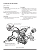
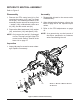
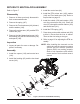
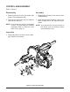
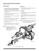
Refer to Figure 6
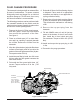
Disassembly
1. Remove the RTN control arm kit by rst
removing the spring (147) and Torx head
screw (46). The remaining members of the
assembly can be removed as a single item
– washer (146), unidirectional scissor arm
kit (145), and the control arm (44).
2. Remove the Allen head screw (142), washer
(45), neutral arm (141) and spacer (140).
NOTE: Onlyremovetheseal(41)ifdamaged
orworn.ThesealisnotpartoftheRTN
controlarmkit.Referto“SealKit”inthe
ItemsListonpage37.
Inspection
1. Inspect all parts for excessive wear or dam-
age. Replace if necessary.
Assembly
1. Reassemble all parts in the reverse order
of disassembly.
2. When tightening the fasteners, refer to the
table on page 20 for the required torque
values.
3. Refer to the RTN adjustments on page
13.
NOTE: Asageneralrule,usethelowendof
the torque specication on fasteners
whenreassemblingtheunit.
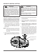
RETURN TO NEUTRAL ASSEMBLY
Figure 6, Return to Neutral Assembly
RefeR to “RetuRn to neutRal Setting”
on Page 13.
41
141
147
142
44
146
145
46
45
140