OPERATOR’S MANUAL SERIES 3000 TRACTOR Model GT 3200 IMPORTANT: READ SAFETY RULES AND INSTRUCTIONS CAREFULLY Warning: This unit is equipped with an internal combustion engine and should not be used on or near any unimproved forest-covered, brush-covered or grass-covered land unless the engine’s exhaust system is equipped with a spark arrester meeting applicable local or state laws (if any). If a spark arrester is used, it should be maintained in effective working order by the operator.
NOTES 2
TABLE OF CONTENTS PAGE TRACTOR PREPARTION . . . . . . . . . . . . . . . . . . . . . . . . . . . . . . . . . . . . . . 4 IMPORTANT SAFE OPERATION PRACTICES . . . . . . . . . . . . . . . . . . . . . 5 CALLING SERVICE INFORMATION . . . . . . . . . . . . . . . . . . . . . . . . . . . . . . 9 FINDING YOUR MODEL & SERIAL NUMBER . . . . . . . . . . . . . . . . . . . . . . 9 SAFETY LABELS FOUND ON YOUR UNIT . . . . . . . . . . . . . . . . . . . . . . . 10 CONTROLS AND FEATURES . . . . . . . . . . . . . . . . . . .
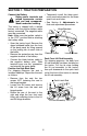
SECTION 1: TRACTOR PREPARATION Connect the Battery Battery posts, terminals and related accessories contain lead and lead compounds. Wash hands after handling. • Temporarily install the three previously removed screws into the three open front seat holes. • See Section 8: Adjustments for final seat adjustment procedures. The tractor is shipped with a sealed battery, with the positive battery cable factory connected. The negative cable must be connected.
SECTION 2: IMPORTANT SAFE OPERATION PRACTICES WARNING: THIS SYMBOL POINTS OUT IMPORTANT SAFETY INSTRUCTIONS WHICH, IF NOT FOLLOWED, COULD ENDANGER THE PERSONAL SAFETY AND/OR PROPERTY OF YOURSELF AND OTHERS.READ AND FOLLOW ALL INSTRUCTIONS IN THIS MANUAL BEFORE ATTEMPTING TO OPERATE YOUR UNIT. FAILURE TO COMPLY WITH THESE INSTRUCTIONS MAY RESULT IN PERSONAL INJURY. WHEN YOU SEE THIS SYMBOL, HEED ITS WARNING.
• Your mower is designed to cut normal residential grass of a height no more than 10". Do not attempt to mow through unusually tall, dry grass (e.g., pasture) or piles of dry leaves. Debris may build up on the mower deck or contact the engine exhaust presenting a potential fire hazard. • Use only accessories approved for this machine by the manufacturer. Read, understand and follow all instructions provided with the approved accessory. • Never leave a running machine unattended.
• Avoid starting or stopping on a slope. If tires lose traction, disengage the blade(s) and proceed slowly straight down the slope. • Follow the manufacturers recommendations for wheel weights or counterweights to improve stability. • Use extra care with grass catchers or other attachments. These can change the stability of the machine. • Before and when backing, look behind and down for small children. • Never carry children, even with the blades off.
• Check brake operation frequently. Adjust and service as required. • To reduce fire hazard, keep the machine free of grass, leaves or other debris build-up. Clean up oil or fuel spillage. Allow machine to cool at least 5 minutes before storing. • Muffler, engine and belt guards become hot during operation and can cause a burn. Allow to cool down before touching. • Before cleaning, repairing or inspecting, make certain the blade and all moving parts have stopped.
SECTION 3: CALLING SERVICE INFORMATION The engine manufacturer is responsible for all engine-related issues with regards to performance, power-rating, and specifications. If you have difficulties with the unit, have any question regarding the operation or maintenance of this equipment, or desire additional information not found in this manual, contact your dealer.
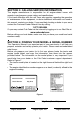
SECTION 5: SAFETY LABELS FOUND ON YOUR UNIT DECK HEIGHT ADJUSTMENT (360 Turn Equals 1/2" Adjustment) 1.RAISE DECK LIFT LEVER UNTIL THE NUMBER 6 APPEARS IN WINDOW. POSITION INDICATOR 2.TURN KNOB COUNTER CLOCKWISE TO LOWER DECKSTOP. 3. TURN KNOB CLOCKWISE TO RAISE DECKSTOP. DANGER WARNING ROTATING BLADES CAUSE SERIOUS INJURY OR DEATH TO ENSURE SAFE AND PROPER OPERATION OF TRANSMISSION, ONLY USE CUB CADET DRIVE SYSTEM FLUID PLUS.
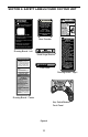
SECTION 6: CONTROLS and FEATURES B A V C U D T E F S Q R P G H I O N J (Not Shown) M K L Figure 3 A B C D E F G H I J K Low Fuel Indicator Lamp Indicator Panel/Hour Meter Key Switch Module Parking Brake Lever PTO Switch Brake Pedal Reverse Pedal Forward Pedal 12V Power Outlet Seat Adjustment Lever (Not Shown) Transmission Release Rod L M N O P Q R S T U V Transmission Oil Fill/Dipstick Fuel Fill Cap Cup Holder Hydraulic Lift Lever Auxiliary Hydraulic Lever Differential Lock Pedal Center Heigh
NOTE: References to LEFT and RIGHT indicate that side of the tractor when facing forward while seated in the drivers seat. Reference to FRONT indicates the grille end of the tractor; to REAR, the drawbar end. Steering Wheel The steering wheel, centered on the dash panel, is used to turn the tractor left or right while driving. NOTE: This tractor is equipped with hydraulic power steering. With this feature, the center of the steering wheel may not stay center aligned. A.
• The hour meter is activated when the key switch is turned to either the “NORMAL MOWING” or the "REVERSE CAUTION MODE" switch positions. A record of the actual hours of operation should be kept to assure maintenance procedures are completed according to the schedule in this manual. • When the key switch is turned to the on position, the battery indicator light briefly illuminates and the battery voltage is briefly displayed. The display then changes to the accumulated hours. C.
H. Forward Pedal D. Parking Brake Lever Figure 6 The parking brake lever is located to the right of the steering wheel in the dash panel. With the brake pedal depressed fully, push the parking brake lever downward and release the brake pedal to lock the parking brake. E. PTO Switch The PTO switch is located on the lower/right side the dash panel. Pull the knob outward to engage the PTO clutch. Push the knob inward to disengage the PTO clutch. F.
M. Fuel Fill Cap The fuel fill cap is located on the fender to the left of the seat. LOWER N. Cup Holder The cup holder is located on the fender to the left of the seat. RAISE O. Hydraulic Lift Lever The hydraulic lift lever is located on the fender to the left of the seat. This lever is used to operate the tractor’s center lift system. P. Auxiliary Hydraulic Lever The auxiliary hydraulic lever is located on the left fender.
IMPORTANT: When using power take-off operated equipment, best performance is achieved with the throttle lever in the “FAST” position. V. Choke Lever The choke lever is located to the left of the steering wheel in the throttle/choke lever pod. Push the lever forward to close the engine choke plate. SECTION 7: OPERATION Safety Interlock Switches This tractor is equipped with a safety interlock system for the protection of the operator.
continuously for more than 10 seconds at a time. If the engine does not start within this time, turn the key to “STOP” and wait a minute to allow the engine’s starter motor to cool. Try again after waiting. motion. Use the brake pedal to bring the tractor to a stop before depressing either the forward or reverse control pedal. • After the engine starts, slowly release the brake pedal. As the engine warms up, gradually pull the choke lever all the way back.
Driving On Slopes Refer to the SLOPE GAUGE on page 41 to help determine slopes where you may not operate safely. WARNING: Do not mow on inclines with a slope in excess of 15 degrees (a rise of approximately 2-1/2 feet every 10 feet). The tractor could overturn and cause serious injury. Operate the tractor up and down slopes, never across slopes.
Using the REVERSE CAUTION MODE key position (Yellow) position of the key switch module. Refer to Figure 12. The REVERSE CAUTION MODE position of the key switch module allows the machine to be operated in reverse with the blades (PTO) engaged. 3. IMPORTANT: Mowing in reverse is not recommended. Use extreme caution while operating the tractor in the “Reverse Caution Mode”. Always look down and behind before and while backing. Do not operate the tractor when children or others are around.
Engaging Differential Lock Fully depress the diff. lock pedal to lock the transmission differential and provide constant power to both rear wheels when increased traction is needed. Release the diff. lock pedal when extra traction is not needed. Depressing the brake pedal also actuates the diff. lock pedal, resulting in optimal braking action. NOTE: Because of the load on the internal engagement mechanism, releasing the diff. lock pedal may not always disengage the differential lock.
SECTION 8: ADJUSTMENTS Seat Adjustment • Seat forward-use front two holes. WARNING: Do not adjust • Seat middle-use middle two holes. the seat when the tractor is moving, as this could cause the operator to lose control of the tractor. For the comfort of the operator, the tractor is equipped with an easy to operate adjustable seat. There are also three seat mounting positions to provide additional adjustment.
Brake Inspection and Adjustment During normal operation, the tractor brake is subject to minimal wear. However, the brake should be periodically tested, and adjusted if necessary. • Turn the nylon lock nut counterclockwise to decrease the braking force. Brake Link Checking the Brake. Place the tractor on a firm and level surface. Stop the engine and remove the ignition key. Pull and lock the transmission release rod in the “Transmission Released” position.
SECTION 9: MAINTENANCE Grease front wheel bearings Grease L/R steering knuckles Grease front pivot axle Check engine oil level Change engine oil and filter Check spark plug condition Check transmission oil level Change transmission oil filter Change transmission oil Check air cleaner & housing Clean & re-oil foam air pre-cleaner Change air cleaner paper cartridge ‡ † †† 300 Hours 250 Hours 200 Hours 150 Hours 100 Hours 50 Hours 10 Hours Operation to be performed Each Use Maintenance Chart • • •
LUBRICATION ILLUSTRATION Transmission 24 L/R Front Wheels Foot Control Pivot Points Engine Oil Can (High quality lubricating oil) Front Pivot Axle Engine Oil: See Figure 27 on page 34 Transmission Oil - Cub Cadet Drive System Fluid Plus - ONLY L/R Steering Knuckle Cub Cadet 251H EP Grease or equivalent No.
Accessing Engine Compartment The engine compartment can be accessed by raising the hood as follows: • Lift the hood straight upward at the recessed notches of the side panels to disengage the internal hood latch. • Carefully pivot the hood forward to open. To close the hood: • Carefully pivot the hood rearward to lower. • Push down on the front of the hood to engage the internal hood latch. If greater access is required, the tractor is equipped with quick release side panels.
• • • • with a solution of ammonia/water or baking soda/water. NEVER connect (or disconnect) battery charger clips to the battery while the charger is turned on, as it can cause sparks. Keep all sources of ignition (cigarettes, matches, lighters) away from the battery. The hydrogen gas generated during charging can be combustible. As a further precaution, only charge the battery in a well ventilated area. Always shield eyes and protect skin and clothing when working near batteries.
Charging the Battery Test and, if necessary, recharge the battery after the tractor has been stored for a period of time. • A voltmeter or load tester should read 12.6 volts (DC) or higher across the battery terminals. • Charge the battery with a 12-volt battery charger at a MAXIMUM rate of 10 amps. Voltmeter State of Reading Charge 12.7 100% 12.4 75% 12.2 50% 12.0 25% Charging Time Full Charge 90 Min. 180 Min. 280 Min. Headlight Bulb Replacement Replace headlight bulbs as follows: (See Figure 20) 1.
then fully reinserted before being withdrawn again for a true reading. F A Dipstick Reading Operating Range Transmission Oil Fill Tube/ Dipstick • Remove the dipstick from the oil fill tube and SLOWLY pour oil into the oil fill tube. Fill the transmission case until the oil level reaches the “FULL” mark on the dipstick. • Reinstall the dipstick securely into the oil fill tube. WARNING: The oil fill plug/ dipstick must be installed securely into the fill tube at all times when the engine is operating.
Oil Filter Transmission Drain Plug Figure 22 • Clean around the base of the transmission oil filter and remove the filter by turning it counterclockwise. • Apply a light coating of clean transmission oil to the gasket of the new filter. Install the filter by turning it clockwise, by hand, until the gasket contacts the filter base on the transmission housing; then tighten the filter an additional 1/2 turn.
Fuse Fuses are installed to protect the tractor’s electrical system from damage caused by excessive amperage. Always use the same capacity fuse for replacement. Refer to the Specifications Chart. If the electrical system does not function, check the fuses. To replace a fuse, note the position of the fuse and pull the old fuse from the electrical box. Compare the suspect fuse with Figure 24 to determine if is good or bad.
SECTION 10: ENGINE INFORMATION KOHLER CO. FEDERAL AND CALIFORNIA EMISSION CONTROL SYSTEMS LIMITED WARRANTY SMALL OFF-ROAD EQUIPMENT ENGINES The U.S. Environmental Protection Agency (EPA), the California Air Resources Board (CARB), and Kohler Co. are pleased to explain the Federal and California Emission Control Systems Warranty on your small off-road equipment engine (herein engine).
LIMITATIONS This Emission Control System Warranty shall not cover any of the following: (a) repair or replacement required because of misuse or neglect, improper maintenance, repairs improperly performed or replacement not conforming to Kohler Co. specifications that adversely affect performance and/or durability, and alterations or modifications not recommended or approved in writing by Kohler Co.
Cleaning The Engine This tractor has an air-cooled engine. Air must be able to circulate freely around the engine through the flywheel screen, through the cooling shrouds and over the fins of the cylinder head and cylinder block. Keep these areas free of accumulated dirt and debris or the engine will overheat; possibly causing extensive engine damage. Regularly clean the inside of the side panels, dash intake screen and grille to ensure adequate cooling.
Refer to Figure 27 for information regarding the proper type of oil to add to the crankcase. • Place the tractor on a level surface and engage the parking brake. Stop the tractor engine and remove the ignition key. • Clean the area around the oil filler cap to prevent debris from entering the crankcase. See Figure 26. • Remove the oil filler cap from the left valve cover and SLOWLY pour in oil. Fill the crankcase until the oil level reaches the “FULL” mark on the dipstick. See Figure 25.
• Attach the flexible tubing to the drain valve. Place an appropriate container below the open end of the tubing to collect the old oil. • To open the drain valve, push it slightly inward and turn it counterclockwise until it stops, then pull it outward. • Remove the filter by turning it counterclockwise using an automotive type filter wrench to loosen. • Allow the old oil to completely drain from the engine crankcase into the container below.
WARNING: Operating the engine with loose or damaged air cleaner components will allow unfiltered air into the carburetor, causing extensive wear and eventual failure of the engine. Servicing The Precleaner Wash and re-oil the foam precleaner more often under extremely dusty or dirty conditions. See Figure 29. • Loosen the aircleaner cover knob and remove the cover. • Remove the foam precleaner by sliding it up off the paper element. • Wash the precleaner in warm water with detergent.
SECTION 11: TROUBLE SHOOTING Possible Cause Possible Remedy Hard To Start No fuel in fuel tank or carburetor Fill the tank with fuel. Check the fuel line, carburetor and fuel filter. Fuel line or carburetor clogged Clean the fuel line and carburetor with a commercial carburetor cleaner. Fuel filter plugged Replace Water in fuel Drain the fuel tank and carburetor. Use new fuel and dry the sparks plugs. Choked improperly.
Possible Cause Fuel tank air vent clogged Possible Remedy Remove obstruction from the vent in the fuel tank cap. Air leakage between carburetor and engine Remove air cleaner. Tighten the carburetor and manifold mounting hardware. Replace any damaged parts as indicated in “MAINTENANCE.” Incorrect timing or faulty ignition See your authorized dealer. Brake dragging Adjust the brakes. Refer to “ADJUSTMENTS.
SECTION 12: OPTIONAL EQUIPMENT When you purchased your tractor, you probably had it completely equipped for your particular needs at that time. However, later you may wish to obtain optional equipment or accessories. These items and other allied equipment can be purchased from, and installed by, your authorized Cub Cadet dealer.
SECTION 13: SPECIFICATIONS Engine Manufacturer . . . . . . . . . . . . . . . . . . . . . . . . . . . . . . . . . . . . . . . . . Kohler Horsepower . . . . . . . . . . . . . . . . . . . . . . . . . . . . . . . . . . . . . . . . . . . . . 25 Cylinders . . . . . . . . . . . . . . . . . . . . . . . . . . . . . . . . . . . . . . 2 (Command) Cooling . . . . . . . . . . . . . . . . . . . . . . . . . . . . . . . . . . . . . . . . . . . . . . . . Air Fast Idle Speed . . . . . . . . . . . . . . . . . . . . . . . . .
SECTION 14: SLOPE GAUGE WARNING: Do not mow on inclines with a slope in excess of 15 degrees (a rise of approximately 2-1/2 feet every 10 feet). A riding mower could overturn and cause serious injury. If operating a walkbehind mower on such a slope, it is extremely difficult to maintain your footing and you could slip, resulting in serious injury. • Operate RIDING mowers up and down slopes, never across the face of slopes.
CUB CADET LLC MANUFACTURER’S ONE YEAR LIMITED WARRANTY (COMMERCIAL USE) The limited warranty set forth below is given by CUB CADET LLC (“CUB CADET”) with respect to new merchandise purchased and used in the United States, its possessions and territories.
No implied warranty, including any implied warranty of merchantability or fitness for a particular purpose, applies after the applicable period of express written warranty above. No other express warranty or guaranty, whether written or oral, except as mentioned above, given by any person or entity, including the dealer, with respect to any product shall bind CUB CADET. During the period of the Warranty, the exclusive remedy is repair or replacement of the product as set forth above.
CUB CADET LLC MANUFACTURER’S LIMITED WARRANTY (RESIDENTIAL USE) The limited warranty set forth below is given by CUB CADET LLC (“CUB CADET”) with respect to new merchandise purchased and used in the United States, its possessions and territories.
b. CUB CADET does not extend any warranty for products sold or exported outside of the United States of America, its possessions and territories, except those sold through CUB CADET’S authorized channels of export distribution. c. Normal wear parts or components, including blades, blade adapters, grass bags, rider deck wheels, seats, snow thrower skid shoes, rubber auger spirals, shave plates and tires. d. Replacement parts that are not genuine Cub Cadet parts. e.
SECTION 15: QUICK REFERENCE PARTS Description Part Number Engine Oil 737-3030A (10W30) 737-3049 (5W30) Air Filter CARTRIDGE FOAM PRE-CLEANER KH-47-083-03 KH-24-083-02 Engine Oil Filter KH-12-050-08 Spark Plug 759-3336 Transmission Oil Cub Cadet Drive System Fluid Plus 737-3120 - Quart 737-3121 - Gallon Transmission Oil Filter 923-3014 Mower Deck Blades Mower Deck Belts PTO Belt (set of 2) 44” Deck -759-3939 (3) 48” Deck -759-3826 (3) 54” Deck -759-3820 (3) 50” Deck -759-04047 (3) 44” Deck - 9