OPERATOR’S MANUAL SERIES 2000 TRACTOR Model Number GT 2186-48 w/48" Mower Deck IMPORTANT: READ SAFETY RULES AND INSTRUCTIONS CAREFULLY Warning: This unit is equipped with an internal combustion engine and should not be used on or near any unimproved forestcovered, brush-covered or grass-covered land unless the engine’s exhaust system is equipped with a spark arrester meeting applicable local or state laws (if any).
KOHLER CO. FEDERAL AND CALIFORNIA EMISSION CONTROL SYSTEMS LIMITED WARRANTY SMALL OFF-ROAD EQUIPMENT ENGINES The U.S. Environmental Protection Agency (EPA), the California Air Resources Board (CARB), and Kohler Co. are pleased to explain the Federal and California Emission Control Systems Warranty on your small off-road equipment engine (herein engine). For California, engines produced in 1995 and later must be designed, built and equipped to meet the state’s stringent anti-smog standards.
CONTENTS Section I II III IV V Emission Control Systems Warranty ... Tractor and Deck Preparation.............. Safe Operation Practices ..................... Product Graphics ................................. To The Owner .................................... Calling Service Information .................. Recording Model & Serial Number ...... Controls and Indicators ........................ Operation ............................................. Adjustments .........................................
WARNING • • • The engine exhaust, some of its constituents, and certain vehicle components contain or emit chemicals known to the State of California to cause cancer, birth defects or other reproductive harm. This unit is equipped with an internal combustion engine and should not be used on or near any unimproved forest-covered, brush-covered, or grass-covered land unless the engine’s exhaust system is equipped with a spark arrester meeting applicable local or state laws (if any).
DO: 13. Mow only in daylight or good artificial light. 14. Do not operate the machine while under the influence of alcohol or drugs. Mow up and down slopes, not across. 15. Watch for traffic when operating near or crossing roadways. Watch for holes, ruts or bumps. Uneven terrain could overturn the machine. Tall grass can hide obstacles. 16. Use extra care when loading or unloading the machine into a trailer or truck.
8. After striking a foreign object, stop the engine, remove the wire from the spark plug and thoroughly inspect the mower for any damage. Repair the damage before restarting and operating the mower. 5. Never allow children under 14 years old to operate the machine. Children 14 years and over should only operate the machine under close parental supervision and proper instruction. 6.
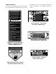
PRODUCT GRAPHICS Keep product safety graphics (decals) clean. Replace any safety graphic that is damaged, destroyed, miss- ing, painted over or can no longer be read. Replacement safety graphics are available through your dealer. STARTING INSTRUCTIONS 1. BE FAMILIAR WITH CONTROLS BEFORE STARTING ENGINE AND OPERATING. 2. SET CHOKE, MOVE THROTTLE TO MID KEEP HANDS AND FEET AWAY FROM ROTATING PARTS. REMOVE OBJECTS THAT CAN BE THROWN BY THE BLADE IN ANY DIRECTION. WEAR SAFETY GLASSES.
TO THE OWNER This Operator’s Manual is an important part of your new tractor. The information contained in this manual has been prepared in detail to help you better understand the features, correct operation, adjustments, and maintenance of your tractor. The performance and dependability of this tractor rely greatly on the manner in which it is operated and maintained. Therefore, it is recommended that all operators of the tractor carefully read this manual and fully understand its operation.
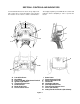
SECTION I. CONTROLS AND INDICATORS Your Cub Cadet Tractor has been safety engineered. This section gives a brief description of the function and location of the various controls and indicators. A Thoroughly acquaint yourself with all the controls and indicators before attempting to start or operate the tractor. B I C J F D K E H G L O M N A. B. C. D. E. F. G. H.
A. LOW OIL INDICATOR This indicator will illuminate when the engine oil level is low. If this indicator illuminates, stop the tractor immediately and check the engine oil level. If the oil level is within the operating range, but the light remains on, contact your Cub Cadet dealer. E. THROTTLE CONTROL LEVER This lever controls the speed of the engine. When set in a given position, the control cable will maintain a uniform engine speed.
I. BRAKE PEDAL The brake pedal is located at the front of the right running board above the forward control pedal. Press down to stop the tractor and disengage the cruise control. The brake pedal must be fully depressed to activate the safety interlock switch when starting the tractor. J. FORWARD CONTROL PEDAL The forward control pedal is located at the front of the right running board below the brake pedal. Slowly press down on the pedal to start moving forward.
Q. SAFETY INTERLOCK SWITCHES This tractor is equipped with a safety interlock system for the protection of the operator. If the interlock system should ever malfunction, do not operate the tractor. Contact your authorized Cub Cadet Dealer. The safety interlock system prevents the engine from cranking or starting unless the brake pedal is fully depressed, and the PTO switch is in the “OFF” position.
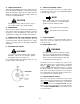
UPPER FRONT WING NUT GRASP REAR WING NUT SIDE PANEL REAR TAB ON PANEL RETAINER WITH TAPERED GUIDE GRILLE GROOVE IN DASH PANEL GRASP Figure 8 13
SECTION II. OPERATION Gasohol (up to 10% ethyl alcohol, 90% unleaded gasoline by volume) is an approved fuel. Other gasoline/alcohol blends are not approved. WARNING Methyl Tertiary Butyl Ether (MTBE) and unleaded gasoline blends (up to a maximum of 15% MTBE by volume) are approved fuels. Other gasoline/ ether blends are not approved. RECEIVE INSTRUCTION - Read the operator’s manual. Learn to operate this machine SAFELY. Don’t risk INJURY or DEATH. 1.
• The safety interlock system will automatically shut off the engine if the operator leaves the seat before engaging the brake pedal lock. • The safety interlock system will automatically disengage the PTO if the reverse control pedal is pressed down with the PTO in the “RUN” position. To re-engage the PTO, release the reverse control pedal, move the PTO switch into the “OFF” position and then engage the PTO while seated.
5. Turn the ingnition key to the “START” position and hold until the engine starts; however, do not crank the engine continuously for more than 10 seconds at a time. Once the engine starts, gradually adjust the choke as needed to keep the engine running until warmed up, then push the choke control all the way in. CAUTION Do not use the forward or reverse control pedals to change the direction of travel when the tractor is in motion.
DRIVING ON SLOPES Refer to the SLOPE GAUGE on page 55 to help determine slopes where you may not operate safely. WARNING Do not mow on inclines with a slope in excess of 15 degrees (a rise of approximately 2-1/2 feet every 10 feet). The tractor could overturn and cause serious injury. 1. Start and run the engine a few minutes to warm up. 2. With the mowing deck, snow thrower, etc.
SECTION III. ADJUSTMENTS This section contains adjustment information for the Model GT 2186 tractor. Adjustment information for the 44-inch deck is located in Section V – Mower Deck beginning on page 33. ADJUSTING THE SEAT WARNING Do not adjust the seat when the tractor is moving. Adjusting the seat while the tractor is moving could cause the operator to lose control of the tractor. Before starting the tractor, adjust the seat forward or rearward to the most comfortable driving position.
WHEEL ALIGNMENT The front wheels should toe-in approximately 1/8 to 1/4 inch, as measured across dimensions A and B shown in Figure 12. PERPENDICULAR TO FRAME 5. Disconnect the front ball joints from the steering arms by removing the hex lock nuts (Refer to Figure 13). Manually move each wheel to achieve the required toe-in and equal D measurements. 6. Loosen the jam nuts from the ball joints (See Figure 13). LOWER STEERING ARM BALL JOINT JAM NUT TIE ROD HEX LOCK NUT STEERING ARM Figure 13 Figure 12.
2. Pivot the ends of the axle up and down to check for binding. If the axle is binding, loosen the lock nuts (See Figure 14) until binding is eliminated. WARNING Place the tractor on a firm and level surface and chock the front wheels before raising the rear wheels from the ground. Use jack stands to support the rear of the tractor when raised. PIVOT AXLE ADJUSTMENT BOLTS LOCK NUT 2. Raise the rear of the tractor, so that the rear tires are at least one inch above the surface, and set it on jack stands.
3 2 4 1. 2. 3. 4. 5. 6. 7. 8. 9. 10. Front Control Rod Rear Control Rod Hex Tap Screw Pivot Sleeve Neutral Arm Control Arm Hex Cap Screw Centering Spacer Neutral Bracket Hairpin Cotter (Not Shown) 5 1 10 6 CONTROL CAM 5 7 8 9 Figure 15.
CARBURETOR ADJUSTMENTS NOTE WARNING When making adjustments to the carburetor while the engine is running, disengage the PTO clutch and engage the brake pedal lock. Keep clear of all moving parts and be careful of all hot surfaces. WARNING Carbon monoxide fumes can be fatal! Do not make any adjustments to the carburetor in a confined area such as a storage building. Move the tractor outside into the air. Carburetor adjustments should be made only after the engine has warmed up. 1.
SECTION IV. MAINTENANCE • ENGINE MAINTENANCE Maintenance, repair, or replacement of the emission control devices and systems, which are being done at the customer’s expense, may be performed by any engine repair establishment or individual. Warranty repairs must be performed by an authorized Kohler service outlet. Never operate the engine with the oil level below the “L” mark or above the “F” mark on the dipstick. NOTE Check the oil level only while the engine is stopped and the tractor is level.
ADDING OIL WARNING CAUTION If the tractor has recently been operated, the engine and surrounding areas may be hot. Use caution not to burn yourself when removing the side panels, draining the oil from the crankcase, and changing the oil filter. Never overfill the engine crankcase. The engine may overheat and/or damage may result if the crankcase is below the “LOW” mark or over the “FULL” mark on the dipstick.
FILLING THE CRANKCASE While the engine oil is warm, proceed as follows: NOTE CAUTION A 12 inch length of flexible tubing is supplied in the owner’s manual package and should be used to drain the engine oil. 1. Place the tractor on a level surface and engage the brake pedal lock. Stop the tractor engine and remove the ignition key. 2. Clean around the base of the oil filter, oil level dipstick, dipstick tube, and the oil filler cap to prevent debris from entering the crankcase. 3.
CHECKING TRANSMISSION OIL LEVEL NOTE Check the oil level only while the engine is stopped and the tractor is level. Check the oil level of the transmission case before each use to see that it is filled to the correct level. Before checking the transmission oil level, clean the area around the oil fill plug/dipstick to prevent debris from entering the transmission case. Always keep the oil level between the “FULL” and the “ADD” marks on the dipstick (See Figure 20).
2. Clean the area around the transmission drain plug to prevent debris from entering the transmission case. Remove the drain plug and allow the transmission oil to drain into a clean container having a capacity of more than 6 quarts. Reinstall the drain plug (Refer to Figure 21). CAUTION If the transmission oil is to be re-used, cover the container holding the drained oil to prevent contamination. Contaminated transmission oil can damage the hydro transmission. TRANSMISSION OIL FILTER Figure 22 7.
1. Unfasten the air cleaner cover retaining knob and remove the air cleaner cover (See Figure 23). 2. Remove the foam precleaner by sliding it up off the paper element (See Figure 23). 3. Remove the wing nut and element cover plate, then lift out the paper air filter element. 1 3 2 4 5 5. When servicing the air cleaner, check the air cleaner base. Make sure it is secured and not bent or damaged. Also check the element cover for damage or improper fit. Replace all damaged air cleaner components.
HEADLIGHTS SPARK PLUG Refer to SPECIFICATIONS when replacement of head lamp bulbs is necessary. WARNING To avoid possible injury, be sure the engine is off and has cooled before making any adjustments or repairs. WARNING Allow the engine and surrounding surfaces to cool before changing the head lamp bulbs. NOTE Replace headlight bulbs as follows: (See Figure 25) 1. Unplug the wire harness leads from the headlight socket terminals. Note which wire connects to each terminal before disconnecting.
FUSES Always use the same capacity fuse for replacement. Refer to SPECIFICATIONS. If the electrical system does not function, check the fuses. To replace a fuse, pull the old fuse from the fuse holder and install the new fuse. MAINTENANCE OF BATTERY GENERAL BATTERY INFORMATION 1. Spray the terminals and exposed wire with a battery terminal sealer, or coat the terminals with a thin coat of grease or petroleum jelly, to protect against corrosion. WARNING a.
4. Pull downward on the bottom of the battery holddown strap to release it from the tab beneath the battery tray. BATTERY REMOVAL OR INSTALLATION WARNING 5. Loosen the hose clamp and pull the drain tube from the battery. Battery posts, terminals and related accessories contain lead and lead compounds. Wash Hands after handling. 6. Lift the battery upward and remove from the left side of the tractor.
CHARGING THE BATTERY Tire SizePounds per Square Inch Test and, if necessary, recharge the battery after the tractor has been stored for a period of time. • A voltmeter or load tester should read 12.6 volts (DC) or higher across the battery terminals. Front Tires 16 x 6.5–8 14 Rear Tires 23 x 9.5–12 10 • Charge the battery with a 12-volt battery charger at a MAXIMUM rate of 10 amps. Voltmeter Reading 12.7 12.4 12.2 12.0 State of Charge 100% 75% 50% 25% Charging Time Full Charge 90 Min. 180 Min.
SECTION V. MOWER DECK A. INSTALLATION AND REMOVAL OF DECK INSTALLATION OF DECK WARNING Before installing the mower deck, place the PTO switch in the “OFF” position, engage the brake pedal lock, turn the ignition key to the “OFF” position and remove the key from the switch. Disconnect the spark plug wires for additional safety. When handling the mower deck, be careful not to cut yourself on the sharp blades. SLIDE UNDER 1. Position the tractor and mower deck on a firm, level surface. 2.
NOTE If installing the deck on a new tractor, cut the cable tie used to hold the front lift rod up during shipment. Then proceed to step 8. 8. While holding the front lift rod up, slide the mower deck forward until the rod aligns with both front roller bracket slots. Lower the lift rod into the front roller bracket slots and slide the deck rearward to engage the lift rod fully forward in the slots of the deck front roller bracket (Refer to Figure 33). 6.
NOTE: It may be necessary to lift each side of the deck and maneuver it slightly to align the support pins with the holes of the lift links. Make certain the support pins are fully extended through the lift links to prevent the mower deck from disengaging the lift links while mowing. LIFT LINKS (BOTH SIDES) 13. Pass the PTO belt upward inside the front of the tractor frame and install the forward end of the belt onto the PTO clutch pulley on the front of the engine.
PTO BELT LIFT ASSIST SPRING MOWER DECK CENTER DOUBLE PULLEY FRONT OF DECK HOLE IN REAR DECK BRACKET Figure 39 17. While holding the belt in position, rotate the deck idler arm lever into its stop bracket to tension the PTO belt (Refer to Figure 40). Make certain the PTO belt is properly positioned in the PTO clutch pulley and both lower front pulleys. Reposition if necessary. STOP BRACKET Figure 42 20.
B. REMOVAL OF DECK LIFT ASSIST SPRING WARNING Before removing the mower deck, place the PTO switch in the “OFF” position, engage the brake pedal lock, turn the ignition key to the “OFF” position and remove the key from the switch. Disconnect the spark plug wires for additional safety. When handling the mower deck, be careful not to cut yourself on the sharp blades. LIFT ASSIST ROD 1. Position the tractor and mower deck on a firm, level surface.
7. Lower the mower deck by moving the implement lift handle to its lowest setting. Disengage the deck idler arm lever from its stop bracket and release the spring tension by rotating the lever out and rearward (Refer to Figure 47). WARNING If the engine has been recently operated, the exhaust system, engine, and surrounding areas will be hot. To avoid personal injury, allow these areas to cool before proceeding with the following PTO belt removal instructions. IDLER ARM LEVER STOP BRACKET 9.
11. Pull the deck support pins outward, turn downward and release so both spring-loaded pins are held in the disengaged position against the outer surface of the deck brackets (Refer to Figure 52). TRACTOR LATCH RECEIVER (BOTH SIDES) QUICK ATTACH ROD SHOULDER BOLT (BOTH SIDES) FRONT LIFT ROD/BRACKET ASSEMBLY LIFT LINK Figure 54 REAR DECK BRACKET DECK SUPPORT PIN DISENGAGED (BOTH SIDES) CAUTION Figure 52 12. Raise the tractor implement lift handle to its highest setting.
B. DECK LEVELING ADJUSTMENTS The 48" mower deck is equipped with ground following front castor wheels and is designed to run on its own wheels. However, to ensure even cutting, the mower deck should be properly leveled. The leveling procedure will result in the left and right blades having corresponding cutting-edge-to ground measurements within 1/16 inch of each other. Also, the blades will have a downward tilt toward the front of the tractor of approximately 1/8 to 1/4 inch.
8. Loosen the upper jam nut on the hanger bracket and turn away from the adjustment ferrule. Turn the lower lock nut upward (tighten) on the threads of the hanger bracket to raise the right side of the mower deck. Turn the lock nut down (loosen) on the threads to lower the right side of the mower deck (Refer to Figure 58). UPPER JAM NUT ADJUSTABLE FERRULE 3. Position the mower blades so the ends of each blade point to the front and the rear of the tractor (Refer to Figure 60).
8. Raise the deck to the highest position. Recheck the blade measurements described in step 4. If the resultant measurements are not correct, repeat steps 5, 6 and 7 until the proper measurements are obtained. NOTE The front lift rod should be against the front of both slots in the deck front roller bracket.
C. MAINTENANCE When removing the blades, use a 1-1/4 inch wrench to hold the hex shaped hub of the pulley when loosening the hex nut securing the blade. A block of wood may be placed between the deck housing and the cutting edge of the blade to assist in removal of the hex nut securing the blade (Refer to Figure 64).
Every 50 hours, or twice yearly, lubricate the double pulley with 251H EP grease or an equivalent No. 2 multipurpose lithium grease. Do not over lubricate. Refer to Figure 65. 1 5 2 7 2. Remove the hardware that secures the spindle belt covers to the deck. 3. Remove the spindle belt covers to expose the belt. 1 6 1. Disengage the idler arm lever from its stop bracket and rotate the lever to the outside of the deck to release the spring tension. 4.
SECTION VI. OFF-SEASON STORAGE If the machine is to be inoperative for a period longer than 30 days, the following procedures are recommended: 2. If emptying the fuel system: WARNING Do not drain fuel when the engine is hot. Allow the engine adequate time to cool. Drain fuel into an approved container outdoors, away from open flame.
SECTION VII. MOWING MOWING WARNING To avoid possible injury, do not allow anyone in the area opposite the discharge chute while mowing. Although the area has been supposedly cleared of foreign objects, small objects may be picked up and discharged by the mower. WARNING Never direct the discharge of material toward bystanders or allow anyone near the machine while in operation. For best results it is recommended that the first two laps should be cut with the discharge thrown towards the center.
OPTIONAL EQUIPMENT AND ACCESSORIES When you purchased your tractor, you probably had it completely equipped for your particular needs at the time. However, later you may wish to obtain optional equipment or accessories. These items and other allied equipment can be purchased from, and installed by, your authorized Cub Cadet dealer.
MAINTENANCE CHART Operation to be performed Before each use Clean grille, engine air inlet screen, dash intake screen and side panel screens 10 hours or once a month 30 hours or three times a season 50 hours or twice a season X Fill fuel tank X Change engine oil & oil filter Replace transmission oil filter More often under dirty conditions X X After first 10 hours X Clean & re-oil foam air precleaner X Check battery terminals and case X Grease front axle pivot bolt X Grease steering knuckl
TROUBLE SHOOTING Possible Cause Possible Remedy HARD TO START No gasoline in fuel tank or carburetor ..................... Fill the tank with gasoline. Check the fuel line, carburetor and fuel filter. Fuel line or carburetor clogged................................ Clean the fuel line and carburetor with a commercial carburetor cleaner. Fuel filter plugged.................................................... Replace. Water in gasoline.....................................................
TROUBLE SHOOTING Possible Cause Possible Remedy LACK OF POWER Air cleaner clogged ................................................. Service the air cleaner element. Refer to “MAINTENANCE.” Engine overload ...................................................... Reduce the load. Engine overheated.................................................. Make sure the air intake screen, shrouding, engine fins, side panels, dash intake screen and grille are free of accumulated dirt and debris.
LUBRICATION TABLE Check at Hours Change at Hours Capacity Engine crankcase Check before each use 100 Approx. 4 pints Hydro transmission and transaxle with filter Check before each use Add as needed Approx. 6 qts Point of Lubrication Anticipated Air Temperature Above + 32°F Below + 32°F Cub Cadet Engine Oil SAE 10W30 Cub Cadet Engine Oil SAE 5W20 or 5W30 Cub Cadet Drive System Fluid Plus NOTE: Cub Cadet Drive System Fluid Plus is specially formulated for this application.
LUBRICATION GUIDE WARNING The service life and reliability of any machine depends upon the care it is given. Proper lubrication is a very important part of that care. This lubrication schedule reflects the minimal requirements to maintain the equipment. More frequent inspections and maintenance is preferable. NOTE: We do not recommend the use of a pressure washer or garden hose to clean your unit. They may cause damage to electrical components; spindles; pulleys; bearings; or the engine.
LUBRICATION GUIDE —Before Each Use 1. Engine filler cap and Check the oil (with the engine stopped) and add sufficient new oil to bring it to dipstick the “FULL” mark on the dipstick. Do not overfill. Do not operate the engine if the oil level is below the “LOW” mark on the dipstick. 2. Transmission oil level and fill port Check the oil with the engine stopped. Keep the lubricant up to the “FULL” mark on the dipstick. NOTE: The transmission oil level and fill port services the following: 1. Rear axle 2.
— 12 10 — 6 CHECK OIL — 2 LEVEL BEFORE EACH USE 50 50 — 13 10 — 8 12 — 50 50 — 14 10 — 7 10 — 4 50 — 11 100 — 15 10 — 6 10 — 6 50 — 13 50 — 12 10 — 5 30 — 10 1— BOTH SIDES 30 — 9 BOTH SIDES 10 — 3 LEFT SIDE 100 — 16 CHECK OIL LEVEL BEFORE EACH USE LUBRICATION GUIDE
NE, R WARNING 15° N DO TTE D LI EPR ES ENT ING A 15 ° SL OPE Do not mow on inclines with a slope in excess of 15 degrees (a rise of approximately 2-1/2 feet every 10 feet). A riding mower could overturn and cause serious injury. If operating a walk-behind mower on such a slope, it is extremely difficult to maintain your footing and you could slip, resulting in serious injury. Operate RIDING mowers up and down slopes, never across the face of slopes.
SPECIFICATIONS GT 2186 CAPACITIES Fuel Tank ........................................................................ Crankcase (approximately) ............................................. Transmission Case (approximately) ................................ HYDROSTATIC DRIVE Speed: Forward................................................................ Reverse ................................................................ ENGINE Make and Model ..............................................................
CUB CADET CORPORATION MANUFACTURER’S ONE YEAR LIMITED WARRANTY (COMMERCIAL USE) The limited warranty set forth below is given by CUB CADET LLC (“CUB CADET”) with respect to new merchandise purchased and used in the United States, its possessions and territories.
CUB CADET CORPORATION MANUFACTURER’S LIMITED WARRANTY (RESIDENTIAL USE) This limited warranty does not provide coverage in the following cases: The limited warranty set forth below is given by CUB CADET CORPORATION (“CUB CADET”) with respect to new merchandise purchased and used in the United States, its possessions and territories.
MAINTENANCE PARTS CHART MODEL GT 2186 SERIES 2000 20 HP KOHLER Engine Oil Requirements approx. . . 4 pints ENGINE OIL Part No. Cub Cadet engine oil Ambient temperature viscosity (Grade SG,SH,SJ or higher) Above +32°F SAE 10W30 737-3030A (10W30) Below +32°F SAE 5W20 or 5W30 737-3049 (5W30) Air Filter Requirements AIR FILTER CARTRIDGE Part No. Clean air filter per instructions in your Operator’s Manual . . . . under Maintenance - Air cleaner.