Safe Operation Practices • Set-Up • Operation • Maintenance • Service • Troubleshooting • Warranty Operator’s Manual GTX2154LE WARNING READ AND FOLLOW ALL SAFETY RULES AND INSTRUCTIONS IN THIS MANUAL BEFORE ATTEMPTING TO OPERATE THIS MACHINE. FAILURE TO COMPLY WITH THESE INSTRUCTIONS MAY RESULT IN PERSONAL INJURY. CUB CADET LLC, P.O. BOX 361131 CLEVELAND, OHIO 44136-0019 Printed In USA Form No.
1 To The Owner Thank You Thank you for purchasing a Cub Cadet Garden Tractor. It was carefully engineered to provide excellent performance when properly operated and maintained. Please read this entire manual prior to operating the equipment. It instructs you how to safely and easily set up, operate and maintain your machine. Please be sure that you, and any other persons who will operate the machine, carefully follow the recommended safety practices at all times.
Important Safe Operation Practices 2 WARNING! This symbol points out important safety instructions which, if not followed, could endanger the personal safety and/or property of yourself and others. Read and follow all instructions in this manual before attempting to operate this machine. Failure to comply with these instructions may result in personal injury. When you see this symbol.
12. A missing or damaged discharge cover can cause blade contact or thrown object injuries. 13. Stop the blade(s) when crossing gravel drives, walks, or roads and while not cutting grass. 14. Watch for traffic when operating near or crossing roadways. This machine is not intended for use on any public roadway. Slopes are a major factor related to loss of control and tip-over accidents which can result in severe injury or death. All slopes require extra caution.
Service Children 1. Tragic accidents can occur if the operator is not alert to the presence of children. Children are often attracted to the machine and the mowing activity. They do not understand the dangers. Never assume that children will remain where you last saw them. a. Keep children out of the mowing area and in watchful care of a responsible adult other than the operator. b. Be alert and turn machine off if a child enters the area. c.
Periodically check to make sure the blades come to complete stop within approximately (5) five seconds after operating the blade disengagement control. If the blades do not stop within the this time frame, your machine should be serviced professionally by an authorized Cub Cadet Service Dealer. Do not modify engine 4. Check brake operation frequently as it is subjected to wear during normal operation. Adjust and service as required. Notice Regarding Emissions 5.
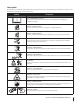
Safety Symbols This page depicts and describes safety symbols that may appear on this product. Read, understand, and follow all instructions on the machine before attempting to assemble and operate. Symbol Description READ THE OPERATOR’S MANUAL(S) Read, understand, and follow all instructions in the manual(s) before attempting to assemble and operate DANGER— ROTATING BLADES Never carry passengers. Never carry children, even with the blades off.
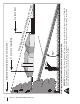
Section 2 — Important Safe Operation Practices d line dotte (repr esent ing a 15° s lope) or a fence post WARNING! Do not operate your lawn mower on such slopes. Do not mow on inclines with a slope in excess of 15 degrees (a rise of approximately 2-1/2 feet every 10 feet). A riding mower could overturn and cause serious injury. Operate riding mowers up and down slopes, never across the face of slopes. Use this page as a guide to determine slopes where you may not operate safely.
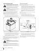
3 Assembly & Set-Up Contents of Crate • One Lawn Tractor • One Operator’s Manual • One Steering Wheel Assembly • One Engine Operator’s Manual NOTE: This Operator’s Manual covers several models. Tractor features may vary by model. Not all features in this manual are applicable to all tractor models and the tractor depicted may differ from yours. Warning! Make sure the lawn tractor’s engine is off, set the parking brake and remove the ignition key before removing the shipping brace. 1.
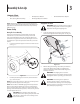
Connecting the Battery Cables California Proposition 65 Warning! Battery posts, terminals, and related accessories contain lead and lead compounds, chemicals known to the State of California to cause cancer and reproductive harm. Wash hands after handling. Caution: When attaching battery cables, always connect the POSITIVE (red) wire to its terminal first, followed by the NEGATIVE (black) wire.
Adjusting the Suspension Seat Refer to Fig. 3-5 for suspension seat adjustments. Suspension Adjustment Lever Tilt Adjustment Knob Seat Adjustment Lever Figure 3-5 To adjust the position of the seat, pull the seat adjustment lever to the right, slide the seat forward or rearward to the desired position; then release the adjustment lever. To adjust the tilt of the seat, rotate the tilt adjustment knob clockwise to tilt the seat back and counter-clockwise to tilt the seat forward.
4 Controls & Features Choke Control Cruise Control/ Parking Brake Lever Throttle Control Brake Pedal Steering Tilt Lever Cup Holder Hour Meter/Service Indicator PTO/Blade Engage Lever Ignition Switch Module Forward Drive Pedal Reverse Drive Pedal Electric Lift Switch Storage Compartment Cutting Height Lever Fuel Cap Hydrostatic Transmission Dipstick/Fill Tube Low Gas Window Transmission Bypass Rod Figure 4-1 Garden Tractor controls and features are illustrated in Fig 4-1 and Throttle Control Lever
Electric Lift Switch LOWER DECK ELECTRI C DECK LIFT RAISE DECK Reverse Pedal To Operate Electric Deck Lift Height Adjustment Raise Electric Deck Lift To The Highest Position. Set Cutting Height. Lower Electric Deck Lift To Chosen Cutting Position. The electric lift switch located in the right fender and is used to raise and lower the deck. To lower the deck press down on the front of the switch and to raise the deck push down on the rear of the switch.
Transmission Bypass Rod The transmission bypass rod is located at the rear of the tractor on the lower right section of the frame. When engaged, the rod opens a bypass within the hydrostatic transmissions, which allows the tractor to be pushed short distances by hand. Refer to the Assembly & Set-Up section for instructions on using the bypass feature. NOTE: If the tractor will not move or does not move freely when pushing check if the bypass lever is fully open.
5 Operation WARNING AVOID SERIOUS INJURY OR DEATH • GO UP AND DOWN SLOPES, NOT ACROSS. • AVOID SUDDEN TURNS. • DO NOT OPERATE UNIT WHERE IT COULD SLIP OR TIP. • IF MACHINE STOPS GOING UPHILL, STOP PTO AND BACK DOWN HILL SLOWLY. • KEEP SAFETY DEVICES [GUARDS, SHIELDS, AND SWITCHES] IN PLACE AND WORKING. • REMOVE OBJECTS THAT COULD BE THROWN BY THE BLADES. • KNOW LOCATION AND FUNCTION OF ALL CONTROLS. • BE SURE THE BLADES AND THE ENGINE ARE STOPPED BEFORE PLACING HANDS OR FEET NEAR BLADES.
Stopping the Engine Warning! If you strike a foreign object, stop the engine and disconnect the spark plug wire(s). Thoroughly inspect the machine for any damage. Repair the damage before restarting and operating 1. If the blades are engaged, place the PTO/Blade Engage lever in the OFF position. 2. Place the throttle control near the SLOW 3. Turn the ignition key counterclockwise to the STOP position. 4. Remove the key from the ignition switch to prevent unintended starting. 3.
Driving On Slopes Setting The Cruise Control Warning! Never engage the cruise control lever while traveling in reverse. Refer to the SLOPE GAUGE on page 8 to help determine slopes where you may operate the tractor safely. WARNING! Do not mow on inclines with a slope in excess of 15 degrees (a rise of approximately 2-1⁄2 feet every 10 feet). The tractor could overturn and cause serious injury. To set the cruise control: 1. Slowly press the forward drive pedal until the desired speed is achieved. 2.
Engaging the PTO Mowing Warning! To help avoid blade contact or a thrown object injury, keep bystanders, helpers, children and pets at least 75 feet from the machine while it is in operation. Stop machine if anyone enters the area. Engaging the PTO transfers power to the cutting deck or other (separately available) attachments. To engage the PTO: 1. Move the throttle control lever to the FAST 2. Pull the PTO/Blade Engage lever position. See Fig. 5-3. position.
6 Maintenance & Adjustments Maintenance Schedule Before Each use Check/Clean Engine Intake Screen Check Transmission Oil Every 25 Hours Every 50 Hours P Every 100 Hours Prior to Storing P P P Clean Hood/Dash Louvers Check Engine Oil Level Every 10 Hours P P P Change Transmission Oil & Filter * Clean Battery Terminals Lube Front Axles and Rims Lube Front Deck Wheels Lube Deck Spindles Lube Pedal Pivot Points P P P P P P P P P P * — For break-in operation, change after the first 10 hours of u
To refill the oil, re-install the square head plug at the end of the hose and refer to the Engine Operator’s Manual for refilling instructions, oil type and amount. 3. Remove the drain plug and allow the transmission oil to drain into a clean container having a capacity of more than six quarts. Reinstall the drain plug. See Fig. 6-3.
Cleaning the Tractor 4. Any fuel or oil spilled on the machine should be wiped off promptly. Do NOT allow debris to accumulate around the cooling fins of the engine, the transmission’s cooling fan or on any other part of the machine, especially the belts and pulleys. Attach the hose coupler to the water port on your deck. See Fig. 6-5. Nozzle Adapter Cleaning the Engine Intake Screen The engine intake screen area is located on the lower half of the dash.
Lubrication Warning! Before lubricating, repairing, or inspecting, always disengage PTO, set parking brake, stop engine and remove key to prevent unintended starting. Front Wheel Axles Each of the front wheel axles and rims is equipped with a grease fitting. See Fig. 6-6. Lubricated after every 10 hour of operation with Cub Cadet 251H EP grease, or an equivalent No. 2 multipurpose lithium grease. 3. Using a pressure lubricating gun, apply 251H EP grease, or an equivalent No.
1. Deck Spindles The deck spindles should be lubricated after every 10 hour of operation. Grease fittings can be found on top of each spindle bolt. See Fig. 6-9. Lubricate with 251H EP grease or an equivalent No. 2 multi-purpose lithium grease. Using a grease gun, apply two pumps (minimum) or sufficient grease to the spindle shaft. Grease Fittings Park the tractor on a firm, level surface and place the lift lever in a middle position.
3. Loosen, but do NOT remove, the hex bolt on the left deck hanger bracket. See Fig. 6-11. Steering/Toe-in Adjustment To adjust front wheel toe-in, proceed as follows: 1. Check the steering gear to ensure it is in the centered position. The hole in the steering segment gear will align with the hole in the steering housing (See Fig. 6-12). NOTE: A 5⁄16” pin can be used in the alignment holes to assure the steering segment is centered. Adjustment Gear Hex Bolt 2.
Pivot Bar Adjustment Caution: The tractor should be checked every 50 hours of operation for play between the frame channel and the pivot bar. Check and adjust the pivot axle as follows: 1. Raise the front of the tractor and set it on jack stands, so the front wheels are suspended above the ground. WARNING! When jacking up the front end of the tractor, always chock the rear wheels to prevent the tractor from rolling, tipping or sliding off the jack stands. 2.
7 Service Battery 3. Note which battery tray hole the RH side of the hold-down rod is hooked into. Common Causes For Battery Failure 4. Rotate the hold-down rod upward, over and around the battery to unhook from the battery tray. 5. Loosen the hose clamp and pull the drain tube from the battery. 6. Lift the battery out off the battery tray and remove from the tractor. 7. Position the new battery and lower into the battery tray. 8.
Headlights Cutting Deck Removal WARNING! Before removing the mower deck, place the PTO switch in the “OFF” position, engage the parking brake, turn the ignition key to the “OFF” position and remove the key from the switch. Disconnect the spark plug wire for additional safety. Refer to Replacement Parts section when replacement of headlight bulbs is necessary. Replace headlight bulbs as follows: 1. Fully raise the hood of the tractor. 2. Unplug the wire harness leads from the headlight socket terminals.
8. Pull the deck support pin outward to release the deck from the lift arm. See FIg. 7-4. 3. Align the tractor’s lift links with deck support pins found on the rear deck brackets. See Fig. 7-5. Figure 7-5 Figure 7-4 9. Repeat the above steps on the tractor’s right side. 4. 10. Move the lift lever into the top notch to raise the lift links up and out of the way. Use the lift switch to lower the lift links into the lowest cutting position. 5.
6. Remove and retain the lock nuts from each end of the front hanger. Position the hanger over the hooks found on the front of cutting deck, with the angled ends facing upward.. 7. Insert the ends of the front hanger through the holes in the front hanger bracket and secure with the two lock nuts removed earlier. See Fig. 7-7. 2. Feed the belt rearward, toward the deck drive pulley found on the cutting deck. 3.
Blade Care Changing the Deck Belt WARNING! Shut the engine off and remove ignition key before removing the cutting blade(s) for sharpening or replacement. Protect your hands by using heavy gloves when grasping the blade. WARNING! Periodically inspect the blade and/or spindle for cracks or damage, especially after you have struck a foreign object. Do not operate the machine until damaged components are replaced. To remove the blades, proceed as follows: 1. 2.
8 Troubleshooting Problem Excessive vibration Mower will not mulch grass Uneven cut Cause Remedy 1. Cutting blade loose or unbalanced. 1. Tighten blade and spindle. 2. Damaged or bent cutting blade. 2. Replace blade. 1. Engine speed too low. 1. Place throttle in FAST (rabbit) position. 2. Wet grass. 2. Do not mulch when grass is wet. 3. Excessively high grass. 3. Mow once at a high cutting height, then mow again at desired height or make a narrower cutting swath. 4. Dull blade. 4.
9 Replacement Parts Component Part Number and Description 759-3336 Spark Plug KH-24-083-02-S Pre-Cleaner KH-47-083-02-S Air Filter Element KH-12-050-01-S Oil Filter KH-24-050-13-S Fuel Filter 723-3014 Transmission Oil Filter 954-04118 Deck Belt 954-04055 PTO Belt 02005018 Deck Blade, 19” 918-3129C Deck Spindle Phone (800) 965-4CUB to order replacement parts or a complete Parts Manual (have your full model number and serial number ready).
Component Part Number and Description 634-3159 Deck Wheel 925-1707D Battery 751-11817 Fuel Cap 925-0963 12V Bulb 746-04759 Choke Control Cable 746-04771 Throttle Control Cable 925-2054A Ignition Key 01006693 Discharge Chute Assembly Phone (800) 965-4CUB to order replacement parts or a complete Parts Manual (have your full model number and serial number ready). Parts Manual downloads are also available free of charge at www.cubcadet.
FEDERAL and/or CALIFORNIA EMISSION CONTROL WARRANTY STATEMENT YOUR WARRANTY RIGHTS AND OBLIGATIONS MTD Consumer Group Inc, the United States Environmental Protection Agency (EPA), and, for those products certified for sale in the state of California, the California Air Resources Board (CARB) are pleased to explain the emission (evaporative and/or exhaust) control system (ECS) warranty on your outdoor 2006 and later small off-road spark-ignited engine and equipment (outdoor equipment engine) In California, n
WARRANTED PARTS: The repair or replacement of any warranted part otherwise eligible for warranty coverage may be excluded from such warranty coverage if MTD Consumer Group Inc demonstrates that the outdoor equipment engine has been abused, neglected, or improperly maintained, and that such abuse, neglect, or improper maintenance was the direct cause of the need for repair or replacement of the part.
CUB CADET LLC MANUFACTURER’S LIMITED WARRANTY FOR SERIES 2000 TRACTORS IMPORTANT: To obtain warranty coverage owner must present an original proof of purchase and applicable maintenance records to the servicing dealer. Please see the operator’s manual for information on required maintenance and service intervals. In the U.S.A.: Check your Yellow Pages, or contact Cub Cadet LLC at P.O. Box 361131, Cleveland, Ohio 44136-0019, call 1-877-282- 8684 or log on to our website at www.cubcadet.com.