Figure 24 NOTE: This Operator's Manual covers several models. Tractor features may vary by model, Not all features In this manual are applicable to all tractor models and the tractor depicted may differ from yours. NOTE: All references in this manual to the left or right side and front or back of the tractor are from the operating position only, Exceptions, if any, will be specified.
OPERATION 3. Electronic Governor Control {If equipped) When set ina given position, a uniform engine speed will be maintained, The electronic governor control has various inputs for maintaining engine speed, Use CUT setting for optimal cutting performance in normal cutting conditions.
(ogi [e) 1. PTO {BLADE ENGAGE) LEVER (MANUAL PTO) Activating the PTO {Blade Engage} Lever engages power to the cutting deck or other (separately available) attachments. See Engaging the PTO (Blade Engage] (Manual PTO tractors) section for information and instructions on using the PTO, J. TRANSMISSION BYPASS ROD When engaged, the rod opens a bypass within the hydro static transmission, which allows the tractor te be pushed short distances by hand.
lo Tie P. DIFFERENTIAL LOCK PEDAL (IF EQUIPPED) Activating the differential lock increases traction by maintaining equal wheel speed on the rear tires. See Using the Differential Lock section for more information on using the differential lock, Q. SEAT ADJUSTMENT LEVER The seat adjustment lever allows for adjustment forward or backward of the operator's seat.
OPERATION AN CAUTION Do not hold the key In the START position for finger than ten seconds at a time. Doing so may cause damage to your engine's electric starter, 7. Ashe engine warms up, disengage the choke control, Do not use the choke control te enrich the fuel mixture, except as necessary to start the engine, 8. Allow the engine to run for a few minutes at mid-throttle before putting the engine under load.
USING JUMPER CABLES TO START ENGINE A WARNING Batteries contain sulfuric ald and traduce explosive gases. Make certain the area is well ventilated, wear gloves and eye protection, and avoid sparks or flames near the battery, If the battery charge is not sufficient to crank the engine, recharge the battery. Ifa battery charger is unavailable and the tractor must be started, the aid of a booster battery will be necessary, Connect the booster battery as follows: 1.
OPERATION 2. Press down on the park brake/cruise control fever and hold it in'that position. 3. Remove your foot from the forward drive pedal. 4. Release pressure from the park brake/cruise control lever. The forward drive pedal should remain in the down position and the tractor will maintain the same forward drive speed. If it doesn't, the cruse control is not engaged.
OPERATION 4, Once activated {indicator Tight ON), the tractor can be driven in reverse with the cutting PTO (Blade Engage) Lever in the engaged (ON) position, . Always look down and behind before and while backing to make sure ne children are around. After resuming forward motion, press the REVERSE CAUTION MODE button te rectum to NORMAL MOWING. . The REVERSE CAUTION MODE will remain activated until: The REVERSE CAUTION MORE button is pressed again. The ignition key is pressed or removed.
$10] «Do NOT attempt to mow heavy brush and weeds or extremely tall grass. Your tractor is designed to mow lawns, NOT clear brush, + Keep the blades sharp and replace the blades when worn, «+ When approaching the other end of the strip, slow down or stop before turning. A three point turn js recommended. «Align the tractor with an edge of the mowed strip and overlap approximately 3” (7.6 cm).
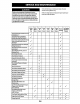
L341 le MAINTENANCE Fallow the Maintenance Schedule given below. This chart describes service guidelines only. A WARNING Before performing any type of maintenance/service, Refer to the Engine Operator's Manual for engine maintenance disengage all controls and stop the engine. Wait until all items listed In the table below. paving parts have come to a complete stop. Allow the able bole engine to cool, Disconnect spark plug wire and ground it against the engine to prevent unintended starting.
RICE AND MAINTENANCE Before| After | Every | Every | Every | Every | Every Prior to) See Engine Each | Fists] 10 25 50 100 | 200 Satori Operator's Use | Hours] Hours | Hours| Hours | Hours | Hours |" “Manual Check Fuel System (Lines, Tank, Cap, Fittings) Check Spark Arrest or Replace Oil Filter Vv v1 Vv ean or Change Alr Filter Vv Vv Replace Fuel Filter Vv Vv Have Valve Lash Checked Vv & Adjusted * Have this item performed by an authorized service dealer, Perform more often in dry conditions and when mulchi
SERVICE AND MAINTENANCE NOTE: Using a pressure washer or garden hose is not recommended for cleaning your tractor other than to clean the underside of the deck. It may cause damage to electrical components, spindles, pulleys, bearings or the engine, The use of water will result in shortened life and reduce serviceability. «Clean under the hood, including exhaust manifold, around fuses, all wiring and harnesses, muffler pipe, muffler shield, engine intake screens and cooling fins, etc. See Figure 30.
RICE AND MAINTENANCE To complete an oil change, proceed as follows: 1. Run the engine for a short time to warm the engine oil, The ofl will flow more freely and carry away more impurities, Use care to avoid burns from hot oil, 2. Open the tractor's hood and Locate the oil drain port on the side of the engine, 3, Place an appropriate ol confection container with at least a 2.5 quart (2.
Ya FV DRE EFY (e Spark Arrest or Maintenance (If equipped) Spark arrest or assemblies must be inspected and cleaned periodically (see the Maintenance Schedule chart in this manual), Visually inspect the screen for teats, broken wires or loose welds. Replace the spark arrest or assembly if any of these conditions exist. if the screen Is in good condition, clean the screen by brushing away loose dirt or carbon particles.
SERVICE AND MAINTENANCE LEVELING THE DECK (SIDE-TO-SIDE) 1. With the tractor parked on a firm, level surface, place the deck lift lever in the middle position and rotate both blades so that they are perpendicular with the tractor. 2. Measure the distance from the outside of the left blade tip to the ground and the distance from the outside of the right blade tip to the ground, Both measurements taken should be equal. If they are not, proceed to the next step. 3.
VICE AND MAINTENANCE PARK BRAKE ADJUSTMENT if the tractor does not come to a complete stop when the brake pedal is completely depressed, or if the tractor’s rear wheels can toll with the park brake applied (and the hydro static relief valve open}, the brake is in dean of adjustment.
SERVICE AND MAINTENANCE 2) “W/ Figure 42 15. Move the deck lift fever into the top notch to raise the deck uplift and out of the way. 16. Gently slide the deck out from underneath the tractor, Removing the Blades PINE Shuttle engine off and remove ignition key before removing the cutting blade(s} for sharpening or replacement. Protect your hands by using heavy gloves when grasping the blade. Periodically inspect the blade and/or spindle for cracks or damage, especially after you've struck a foreign object.
SERVICE AND MAINTENANCE STANDARD BLADE SYSTEM WITH §-BLADES (IF EQUIPPED) 1. Remove the deck from beneath the tractor, {refer to Deck Removal} then gently flip the deck over to expose its underside, . Use a 15/16" wrench to hold the hex nut on top of the spindle assembly when loosening the hex nut (a) and washer (d)* securing the blade (b).
RICE AND MAINTENANCE 2. Where-installing blades, be sure of the following (see Figure 47 on page 32): a. Blades (5) are installed so that wings are pointing upward toward the top of the deck, b. Washer {d)* is placed between bottom of blade (b) and hex nut (3). IMPORTANT! Align "S" shaped cutout with matching “S” shape an spindle for secure fit, 3. Tighten hex nuts (a) to 70-90 ft-lbs {95-122 N-m). 4. Re-stall the deck (refer to Deck Installation in this section). Sharpening the Blade 1.
SERVICE AND MAINTENANCE Re-install the deck making sure the belt remains routed around the pulleys as instructed. , On manual PTO units, re-install the engine pulley keeper rod and the PTO cable, 7 . Pull the right side of the belt and place the narrow *V* side of the belt into the PTO pulley. See Figure 55, Figure 55 10. While holding the belt and pulley together, rotate the pulley to the left, Continue holding and rotating the pulley and belt until the belt is fully rolled Into the PTO pulley.