Safe Operation Practices • Set-Up • Operation • Maintenance • Service • Troubleshooting • Warranty Operator’s Manual Rear Tine Tiller — Model RT 35 WARNING READ AND FOLLOW ALL SAFETY RULES AND INSTRUCTIONS IN THIS MANUAL BEFORE ATTEMPTING TO OPERATE THIS MACHINE. FAILURE TO COMPLY WITH THESE INSTRUCTIONS MAY RESULT IN PERSONAL INJURY. CUB CADET LLC, P.O. BOX 361131 CLEVELAND, OHIO 44136-0019 Printed In USA Form No.
1 To The Owner Thank You Thank you for purchasing a Cub Cadet Garden Tiller. It was carefully engineered to provide excellent performance when properly operated and maintained. If applicable, the power testing information used to establish the power rating of the engine equipped on this machine can be found at www.opei.org or the engine manufacturer’s web site. Please read this entire manual prior to operating the equipment.
2 Important Safe Operation Practices WARNING! This symbol points out important safety instructions which, if not followed, could endanger the personal safety and/or property of yourself and others. Read and follow all instructions in this manual before attempting to operate this machine. Failure to comply with these instructions may result in personal injury. When you see this symbol.
c. When practical, remove gas-powered equipment from the truck or trailer and refuel it on the ground. If this is not possible, then refuel such equipment on a trailer with a portable container, rather than from a gasoline dispenser nozzle. 11. After striking a foreign object, stop the engine, disconnect the spark plug wire and ground against the engine. Thoroughly inspect the machine for any damage. Repair the damage before starting and operating. d.
9. If the fuel tank has to be drained, do this outdoors. 10. Observe proper disposal laws and regulations for gas, oil, etc. to protect the environment. 11. According to the Consumer Products Safety Commission (CPSC) and the U.S. Environmental Protection Agency (EPA), this product has an Average Useful Life of seven (7) years, or 130 hours of operation.
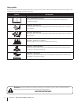
Safety Symbols This page depicts and describes safety symbols that may appear on this product. Read, understand, and follow all instructions on the machine before attempting to assemble and operate. Symbol Description READ THE OPERATOR’S MANUAL(S) Read, understand, and follow all instructions in the manual(s) before attempting to assemble and operate WARNING— ROTATING TINES Do not put hands or feet near rotating parts. Contact with the rotating parts can amputate hands and feet.
3 Assembly & Set-Up Contents of Carton • One Tiller • One Handlebar Assembly • One Engine Operator’s Manual • One Handle Crank w/ Lock Nut NOTE: This Operator’s Manual covers several models. Garden Tiller features may vary by model. Not all features in this manual are applicable to all garden tiller models and the garden tiller depicted may differ from yours. 2.
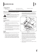
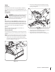
Attaching the Cable 4. To attach the cables, follow these steps: 1. Clip the cable into the cable guide located on the handle assembly panel as seen in Figure 3-3. Route the cable along the handle assembly on the righthand side. See Figure 3-2. Forward Drive Cable Cable Mount Clutch Bail Figure 3-3 Move Tiller Off Crate Figure 3-2 2. Connect the forward drive cable to the clutch bail by feeding the z-hook through the hole on the clutch bail from the outside towards the inside. See Figure 3-2. 3.
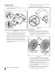
Set-Up 2. Tire Pressure Remove the oil fill plug from the transmission housing cover and locate the main drive shaft situated inside the housing. See Figure 3-6. Check the air pressure with a tire gauge. Deflate or inflate the tires equally to between 15 and 20 PSI. DO NOT EXCEED 20 P.S.I. NOTE: Be sure that both tires are inflated equally or the tiller will pull to one side. Gas & Oil Fill Up WARNING! Use extreme care when handling gasoline.
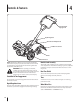
4 Controls & Features Clutch Bail & Tine Engagement Depth Regulator Handle Crank Adjustment Rear Tine Shield Tines Wheel Drive Pin NOTE: This Operator’s Manual covers several models. Garden tiller features may vary by model. Not all features in this manual are applicable to all garden tiller models and the garden tiller depicted may differ from yours.
5 Operation WARNING: Before operating your machine, carefully read and understand this manual and all of its safety, operating and maintenance sections and instructions, along with all of the decals on the machine. Failure to follow these instructions can result in serious personal injury. Introduction Read this Operation Section and the Engine Operator’s Manual before you start the engine. Then, take the time to familiarize yourself with the basic operation of the tiller before using it in the garden.
To Engage Drive & Tines Adjusting the Handle Height 1. For forward motion of the wheels and power to the tines pull the Forward Clutch Bail up against the handlebar. Release the bail to stop the forward motion of wheels and tines. 2. When tilling, relax and let the wheels pull the machine while the tines dig. Walk behind and a little to one side of the tiller. Use one hand, yet keep a light — but secure — grip on the handlebar while keeping your arm loose.
• When cultivating (breaking up the surface soil around the plants to destroy weeds, see Figure 5-3), adjust the tines to dig only 1” to 2” deep. Using the shallow tilling depth helps prevent injury to the plants whose roots often grow close to the surface. If needed, lift up on the handlebars slightly to prevent the tines from digging too deeply. (Cultivating on a regular basis not only eliminates weeds, it also loosens and aerates the soil for better moisture absorption and faster plant growth.
• If the garden size will not permit lengthwise and then crosswise tilling, then overlap the first pass by one-half a tiller width, followed by successive passes at one-quarter width. See Figure 5-6. Terrace Gardening 1. To create a terrace, start at the top of the slope and work down. Go back and forth across the first row as shown in Figure 5-7. UPHILL 1 1 2 2 3 12" UNTILLED 3 1 REPEAT DOWNHILL Figure 5-6 Tilling on a Slope Figure 5-7 2.
Loading & Unloading the Tiller WARNING! Loading and unloading the tiller into a vehicle is potentially hazardous and doing so is not recommended unless absolutely necessary, as this could result in personal injury or property damage. However, if you must load or unload the tiller, follow the guidelines given next. • Before loading or unloading the tiller, stop the engine, wait for all parts to stop moving, disconnect the spark plug wire and let the engine and muffler cool.
6 Maintenance & Adjustments Maintenance Schedule Check After first 2 hours Before each use Every 5 Hours Every 10 Hours Every 30 Hours P Clean Engine Check Drive Belt Tension Check Nuts and Bolts P P P P P Lubricate Tiller P P P Check Gear Oil Level in Transmission Check Tines for Wear Check Air Pressure in Tires WARNING! Before inspecting, cleaning or servicing the machine, shut off the engine, wait for all moving parts to come to a complete stop, disconnect the spark plug wire and move the wir
6. 7. 8. If adding only a few ounces of gear oil, use API rated GL-4 or GL-5 gear oil having a viscosity of SAE 140, SAE 85W-140 or SAE 80W-90. If refilling an empty transmission, use only GL-4 gear oil having a viscosity of SAE 85W-140 or SAE 140. Off-Season Storage While checking frequently to avoid overfilling, slowly add gear oil into the oil fill hole until it reaches the halfway point on the drive shaft. 1. Clean the tiller and engine. 2.
7 Service Belt Replacement 4. If the drive belt need to be replaced, it is best to replace both belts at the same time. Use only a factory-authorized belt as an “over- thecounter” belt may not perform satisfactorily. The procedure requires average mechanical ability and commonly available tools. Remove the idler bracket extension spring from the idler bracket using a pair of needle-nosed pliers.
Removing/Installing a Tine Assembly 1. Remove the tine shield end covers and side shields by removing the three wing nuts on each side that secure them. 2. A tine assembly consists of a left hand tine assembly and a right hand tine assembly. NOTE: The tine assembly moves in a counter-rotating motion with the sharp edges of the tines positioned to enter the soil first when counter-rotating. Note this position of the tines for reinstallation of the new tine assemblies. 3.
8 Troubleshooting Problem Wheels/Tines will not turn Tines turn, but wheels don’t Wheels turn, but tines Don’t Poor tilling performance 20 Cause Remedy 1. Improper use of controls. 1. Review Operation section. 2. Worn, broken, or misadjusted drive belt. 2. Replace or adjust belt. 3. Internal transmission wear or damage. 3. Contact authorized service dealer. 4. Bolt loose in transmission pulley. 4. Tighten bolt. 1. Wheel Drive Pins not in WHEEL DRIVE. 1. Inserts Drive Pins properly. 2.
9 Replacement Parts Component Part Number and Description 954-04090 Forward V-Belt 946-04506 Forward Drive Cable 642-05004 642-05003 911-0415 714-04043 4-Point Tine Assembly (RH) 4-Point Tine Assembly (LH) Clevis Pin, .375 x 1.
Notes 22 10
Section 10 — Notes 23
CUB CADET LLC MANUFACTURER’S LIMITED WARRANTY FOR EDGERS, STRING TRIMMERS & TILLERS The limited warranty set forth below is given by Cub Cadet LLC with respect to new merchandise purchased and used in the United States, its possessions and territories, and by MTD Products Limited with respect to new merchandise purchased and used in Canada and/or its territories and possessions. c.
Normas de seguridad • Configuración • Funcionamiento • Mantenimiento • Reparación y mantenimiento • Solución de problemas • Garantía Manual del Operador Cultivadora de dientes traseros — Modelo RT 35 ADVERTENCIA LEA Y CUMPLA TODAS LAS REGLAS Y LAS INSTRUCCIONES DE SEGURIDAD DE ESTE MANUAL ANTES DE INTENTAR OPERAR ESTA MÁQUINA. SI NO RESPETA ESTAS INSTRUCCIONES PUEDE PROVOCAR LESIONES PERSONALES. CUB CADET LLC, P.O.
1 Al propietario Gracias Gracias por comprar una caña de timón Cub Cadet Jardín. Fue diseñado cuidadosamente para ofrecer un rendimiento excelente cuando se opera y mantiene correctamente. Por favor, lea todo el manual antes de operar el equipo. Le indica cómo de forma segura y fácil de configurar, operar y mantener la máquina. Por favor, asegúrese de que usted, y cualquier otra persona que opera el equipo, siga cuidadosamente las prácticas de seguridad en todo momento.
2 Medidas importantes de seguridad ¡ADVERTENCIA! La presencia de este símbolo indica que se trata de instrucciones importantes de seguridad que se deben respetar para evitar poner en peligro su seguridad personal y/o material y la de otras personas. Lea y siga todas las instrucciones de este manual antes de poner en funcionamiento esta máquina. Si no respeta estas instrucciones puede provocar lesiones personales. Cuando vea este símbolo.
Manejo seguro de la gasolina: Para evitar lesiones personales o daños materiales tenga mucho cuidado cuando trabaje con gasolina. La gasolina es sumamente inflamable y sus vapores pueden causar explosiones. Si se derrama gasolina encima o sobre la ropa se puede lesionar gravemente ya que se puede incendiar. Lávese la piel y cámbiese de ropa de inmediato. a. Utilice sólo los recipientes para gasolina autorizados. b.
4. 5. 6. 7. 8. 9. 10. 11. Antes de limpiar, reparar o inspeccionar la máquina, detenga el motor y asegúrese de que los dientes y todas las partes móviles se hayan detenido. Desconecte el cable de la bujía y póngalo haciendo masa contra el motor para evitar que se encienda accidentalmente. No cambie la configuración del regulador del motor ni lo opere a sobrevelocidad. El regulador del motor controla la velocidad máxima de funcionamiento seguro del motor.
Símbolos de Seguridad Esta página describe los símbolos y figuras de seguridad internacionales que pueden aparecer en este producto. Lea el manual del operador para obtener la información terminada sobre seguridad, reunirse, operación y mantenimiento y reparación. Símbolo Descripción LEA EL MANUAL DEL OPERADOR (S) Lea, entienda, y siga todas las instrucciones en el manual (es) antes de intentar reunirse y funcionar. LA ADVERTENCIA — LOS DIENTES ROTATIVO No ponga manos o pies cerca del giro de partes.
3 Montaje y Configuración Contenido de la caja • Una cultivadora • Un conjunto de barra de control • Un Manual de operación del motor • Un Varilla de manivela y Tuerca NOTA: Este manual de operación cubre distintos modelos. Las características de la cultivadora para jardín pueden variar según los modelos. No todas las características de este manual se aplican a todos los modelos de cultivadoras para jardín y la que se ilustra aquí puede diferir de la suya. 2.
Conexión del cable A fin de conectar los cables, siga estos pasos: 1. Haga pasar el cable a lo largo del conjunto de la manija del lado derecho. Consulte la Figura 3-2. Cable del accionamiento marcha adelante Montaje del cable Gancho del embrague Figura 1-3 Saque la cultivadora de la caja Para hacer rodar la cultivadora fuera de la plataforma de envío, coloque las ruedas de manera que giren libremente, si no vinieron así de fábrica, como se indica: Figura 1-2 2.
NOTA: Antes de poner en marcha el motor, se deben colocar las ruedas en la posición WHEEL DRIVE (transmisión en las ruedas) (trinquetes a través de los cubos de las ruedas y del eje de la rueda). 4. Después de que la cultivadora esté fuera de la caja, ubique las ruedas en la posición WHEEL DRIVE (transmisión en las ruedas), extraiga el trinquete, deslice la rueda completamente hacia adentro y vuelva a colocar el trinquete.
4 Controles y Características Gancho del embrague y activación de los dientes Regulador de profundidad Ajuste de la varilla de manivela Protector de dientes trasero Dientes Trinquete de transmisión en las ruedas NOTA: Este manual de operación cubre distintos modelos. Las características de la cultivadora para jardín pueden variar según los modelos. No todas las características de este manual se aplican a todos los modelos de cultivadoras para jardín y la que se ilustra aquí puede diferir de la suya.
5 Funcionamiento ¡ADVERTENCIA: Antes de operar la máquina, lea con atención y comprenda el presente manual y todas las secciones e instrucciones de seguridad, funcionamiento y mantenimiento que comprende, junto con todas las calcomanías de la máquina. Si no se cumplen dichas instrucciones se pueden producir lesiones personales graves.
1. Lleve a cabo los pasos de la Lista de control previa al arranque mencionada precedentemente. 2. Ubique las ruedas en la posición WHEEL DRIVE (transmisión en las ruedas), para lo cual debe sacar los trinquetes, deslizar la rueda completamente hacia adentro y volver a colocar el trinquete a través de los cubos de la rueda y el eje de la rueda. 3. Mueva la palanca del regulador de profundidad completamente hacia abajo hasta la posición “transporte”, para que los dientes se aparten del suelo. 4.
Sugerencias y técnicas de labranza Profundidad de la labranza ¡ADVERTENCIA! Antes de realizar la labranza, comuníquese con las compañías de teléfono o servicios públicos y consulte si hay equipos/conductos subterráneos en su propiedad. No utilice la cultivadora cerca de cables de electricidad, líneas telefónicas, tuberías o tubos que estén enterrados. • Esta cultivadora tiene dientes contragiratorios (CRT, counterrotating tine). Cuando las ruedas empujan hacia adelante, los dientes giran hacia atrás.
2. Se recomienda realizar la labranza subiendo y bajando las pendientes en lugar de hacerlo según un patrón de terrazas. La labranza vertical en una pendiente permite un área máxima de plantación y además deja espacio para el cultivo. NOTA: Cuando realice la labranza en pendientes, asegúrese de mantener el nivel de aceite correcto en el motor (controle cada media hora de funcionamiento).
borde exterior cuesta abajo de cada terraza. Esta franja sin labrar ayuda a evitar que las terrazas se quiebren y desintegren cuesta abajo. También proporciona una senda para caminar entre las hileras. Limpieza de los dientes • • • Los dientes tienen una acción autolimpiante que elimina la mayor parte de los desechos que se enredan. Sin embargo, a veces se pueden enredar pasto seco, tallos fibrosos o enredaderas resistentes.
6 Mantenimiento y Ajustes Programa de mantenimiento Control al cabo de las primeras 2 horas Controle las tuercas y los pernos Cada 5 horas Cada 10 horas P P P P P Lubrique la cultivadora Controle el nivel de aceite para engranajes de la transmisión P P P Controle el desgaste de los dientes Controle la presión de aire de los neumáticos ¡ADVERTENCIA! Antes de realizar la inspección, la limpieza o el mantenimiento de la máquina, apague el motor, espere hasta que detengan completamente todas las piez
4. El nivel del aceite para engranajes es correcto si dicho aceite está aproximadamente hasta la mitad del lado del eje de accionamiento principal. • 5. Si el nivel del aceite para engranajes es bajo, agregue aceite para engranajes como se describe a continuación. Si el nivel de aceite de engranajes está bien, vuelva a colocar de manera segura el tapón de llenado de aceite.
7 Servicio Cambio de correa Si se desea reemplazar la correa de transmisión, lo mejor es reemplazar ambas correas al mismo tiempo. Use únicamente correas autorizadas por el fabricante, ya que las correas genéricas pueden no desempeñarse satisfactoriamente. El procedimiento requiere habilidad mecánica media y herramientas habitualmente disponibles. Para reemplazar la correa de transmisión y reversa, siga estos pasos: 1.
7. Reemplace la correa vieja por una nueva. Compruebe que la correa quede instalada en las poleas que están más cerca de los dientes/el frente de la cultivadora. 8. Vuelva a colocar el cable de accionamiento en la polea loca. 9. Vuelva a colocar con cuidado el resorte de extensión de la ménsula intermedia en dicha ménsula. 10. Ensamble nuevamente la cultivadora en el orden inverso al seguido para el desensamblado.
8 Solución de Problemas Problema Las ruedas y los dientes no giran Los dientes giran, las ruedas no. Causa 1. Uso incorrecto de los controles. 1. Revise la sección de Funcionamiento 2. Correa de transmisión desgastada, rota o mal ajustada. 2. Reemplace o ajuste la correa. 3. Trasmisión interna desgastada o dañada. 3. Comuníquese con el distribuidor de servicio autorizado. 4. Perno suelto en la polea de transmisión. 4. Ajuste el perno. 1.
Notas 9 45
Section 9 — Notas
Section 9 — Notas 47
GARANTÍA LIMITADA DE CUB CADET LLC PARA BORDEADORA DE CÉSPED, CONTEMPORIZADOR DE CUERDA Y CULTIVADORA DE DIENTES TRASEROS La siguiente garantía limitada es otorgada por Cub Cadet LLC con respecto a nuevos productos adquiridos y utilizados en Estados Unidos, sus posesiones territorios, y por MTD Products Limited con respecto a nuevos productos adquiridos y utilizados en Canadá y/o sus territorios y posesiones. d.