
Operator`s manual


Assembly & Set-Up
3
7
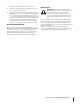
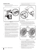
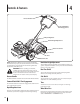
3. Install the handle-crank adjustment rod into the top hole of
the mounting bracket from the left hand side of the handle
assembly, secure with the other flange lock nut previously
removed. Fit the hex end of the retainer bracket over the
flange lock nut. See Figure 3-1.
Figure 3-1
4. Tighten the hex bolt installed in Step 2 at this time. Be
careful not to overtighten this hardware.
5. With the handle in the desired position, tighten the handle-
crank adjustment rod at this time.
NOTE: This Operator’s Manual covers several models. Garden
Tiller features may vary by model. Not all features in this manual
are applicable to all garden tiller models and the garden tiller
depicted may differ from yours.
WARNING! To prevent personal injury or property
damage, do not start the engine until all assembly
steps are complete and you have read and
understand the Safe Operation Practices Section
and the Operating Section in this manual.
Assembly
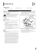
Unpacking Instructions
NOTE: While unpacking, do not severely bend any of the control
cables.
1. The tiller is heavy, do not attempt to remove it from
the shipping platform until instructed to do so in these
assembly steps.
2. Remove all parts from the carton. Check that you have the
items listed in the Contents of Carton list (contact your
local dealer or the MTD technical service representative if
items are missing or damaged).
3. Remove any packaging material from the carton. Remove
any staples from the bottom of the carton and remove the
carton from the shipping platform.
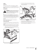
Handle
NOTE: All references to the right or left side of the tiller are from
the operator’s position.
1. Install the handle onto the tiller using the hardware pre-
installed on the handle mounting brackets. This consists of
a ⁄-18 x 3.00 hex bolt, a handle crank assembly, retainer
bracket and two ⁄-18 flange lock nuts. Remove this
hardware from the handle mounting brackets on the tiller.
2. Insert the handle into the handle mounting brackets, lining
up the pre-drilled holes. Insert the ⁄-18 x 3.00 hex bolt
in the bottom hole from the left hand side through to the
other side. Place the round hole end of the hex retainer
bracket over the hex bolt and secure loosely with a bell
washer and ⁄-18 flange lock nut removed earlier.
NOTE: The bell washer should be positioned with the top
of the bell shape towards the hex nut which will create
tension and further secure the flange lock nut once
tightened. Do not tighten this hardware at this time.
Contents of Carton
• One Tiller • One Handlebar Assembly • One Operator’s Manual
• One Engine Operator’s Manual