OPERATOR’S MANUAL RZT SERIES TRACTOR Model Number RZT 50 w/50" Mower Deck IMPORTANT: READ SAFETY RULES AND INSTRUCTIONS CAREFULLY Warning: This unit is equipped with an internal combustion engine and should not be used on or near any unimproved forestcovered, brush-covered or grass-covered land unless the engine’s exhaust system is equipped with a spark arrester meeting applicable local or state laws (if any). If a spark arrester is used, it should be maintained in effective working order by the operator.
TABLE OF CONTENTS TRACTOR PREPARATION .................................................................................................... 2 IMPORTANT SAFE OPERATION PRACTICES ..................................................................... 3 SAFETY DECALS AND LABELS ............................................................................................ 6 TO THE OWNER ....................................................................................................................
WARNING • • • The engine exhaust, some of its constituents, and certain vehicle components contain or emit chemicals known to the State of California to cause cancer, birth defects or other reproductive harm. This unit is equipped with an internal combustion engine and should not be used on or near any unimproved forest-covered, brush-covered, or grass-covered land unless the engine’s exhaust system is equipped with a spark arrester meeting applicable local or state laws (if any).
DO: 13. Mow only in daylight or good artificial light. 14. Do not operate the machine while under the influence of alcohol or drugs. Mow across slopes, not up and down. Keep all movement on the slopes slow and gradual. Do not make sudden changes in speed or direction. Rapid acceleration or deceleration could cause the front of the machine to lift and rapidly flip over backwards, which could cause serious injury. 15. Watch for traffic when operating near or crossing roadways. 16.
8. After striking a foreign object, stop the engine, remove the wire from the spark plug and thoroughly inspect the mower for any damage. Repair the damage before restarting and operating the mower. 5. Never allow children under 14 years old to operate the machine. Children 14 years and over should only operate the machine under close parental supervision and proper instruction. 6.
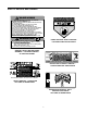
SAFETY DECALS AND LABELS Keep product safety graphics (decals) clean. Replace any safety graphic that is damaged, destroyed, missing, painted over or can no longer be read. Replacement safety graphics are available through your dealer. START FORWARD REVERSE NEUTRAL STARTING INSTRUCTIONS • • • • • To START, PARK BRAKE must be set. P.T.O. switch in OFF (down) position. Lap bars in NEUTRAL and outward positions. Throttle set properly, CHOKE position if "cold".
SAFETY DECALS AND LABELS WARNING TO R ED U CE TH E R IS K O F IN JU R Y, D O N O T O PER ATE U N L ES S D IS CH AR G E CO VER O R GRASS CATCH ER IS IN ITS PR O PER PL ACE. IF D A M A G E D , R E P L A C E IM M E D IA T E L Y . AVOID SERIOUS INJURY OR DEATH • • • • • • • • • • • • • Read The Operator's Manual. Go Across Slopes, Not Up And Down. If Machine Stops Going Uphill, Stop Blade And Back Down Slowly. Avoid Sudden Turns. Do Not Mow When Children Or Others Are Around.
TO THE OWNER This Operator’s Manual is an important part of your new tractor. The information contained in this manual has been prepared in detail to help you better understand the features, correct operation, adjustments, and maintenance of your tractor. The performance and dependability of this tractor rely greatly on the manner in which it is operated and maintained. Therefore, it is recommended that all operators of the tractor carefully read this manual and fully understand its operation.
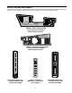
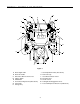
SECTION 1: CONTROLS AND FEATURES B O P C A C N M D E L F F G K H J Figure 3 A. B. C. D. E. F. G. H. Deck Height Index Deck Lift Handle RH and LH Drive Control Levers Ignition Switch PTO Switch Transmission Bypass Rod (Not Shown) Cup Holder Storage Tray J. K. L. M. N. O. P. 9 Seat Adjustment Knobs (Not Shown) Fuel Tank Cap Hour Meter /Indicator Panel Throttle Control Choke Control Parking Brake Engagement Lever Trans.
NOTE: References to LEFT, RIGHT, FRONT, and E. Power Take-Off (PTO) Switch REAR indicate that position on the tractor when facing forward while seated in the operator’s seat. The PTO switch is located on the RH console to the right of the operator’s seat. A. Deck Height Index The deck height index consists of six index notches located on the front/right of the seat box frame.
Oil Pressure Indicator (Refer to Figure 6) WARNING: Never fill the fuel tank when the engine is running. If the engine is hot from recently running, allow to cool for several minutes before refueling. Highly flammable gasoline could splash onto the engine and cause a fire. • L. Hour Meter/Indicator Panel The hour meter/indicator panel is located on the LH console to the left of the operator’s seat.
IMPORTANT: If the LH and RH drive control levers are not fully opened out in the neutral position when engaging the parking brake, the engine will stop. The parking brake must be placed in the engaged position when starting the tractor engine. N. Choke Control The choke knob controls the position of the engine choke. Pull the knob out to choke the engine; push the knob in to open the choke. P.
The PTO will re-engage when one or both of the levers are moved back to the neutral or forward position. BEFORE OPERATING YOUR TRACTOR • Before you operate the tractor, study this manual carefully to familiarize yourself with the operations of all the instruments and controls. It has been prepared to help you operate and maintain your tractor efficiently. • STARTING THE ENGINE WARNING: This unit is equipped with a safety interlock system designed for the protection of the operator.
STOPPING THE ENGINE starter motor to cool. Try again after waiting. If after a few attempts the engine fails to start, do not keep trying to start it with the choke closed as this will cause flooding and make starting more difficult. • • • As the engine warms up, gradually push the choke knob downward to open the choke. Do not use the choke to enrich the fuel mixture, except as necessary to start the engine. Allow the engine to run for a few minutes at mid throttle before putting the engine under load.
• Adjust the operator’s seat to the most comfortable position that allows you to operate the controls. See seat adjustment in the ADJUSTMENTS section. • Release the parking brake. • Move the RH and LH drive control levers inward in the neutral position. See Figure 9.
IMPORTANT: Always maintain your grasp on the drive control levers. Do not release the levers to slow the tractor or to return to neutral. - To turn to the right, move the right drive control lever rearward of the left lever. See Figure 12. FORWARD RIGHT TURN Turning While Driving Rearward • To turn the tractor while driving rearward, move the control levers as necessary so that one lever is forward of the other. The tractor will turn in the direction of the forward control lever.
STOPPING THE TRACTOR • Move both drive control levers to the neutral position to stop the motion of the tractor. Executing a Zero Turn WARNING: When executing a zero turn, the tractor MUST BE STOPPED. Executing a zero turn while the tractor is moving can significantly reduce your control of the tractor and will cause severe turf defacement to occur. • Stop the forward or reverse motion of the tractor by moving the two drive control levers to neutral.
USING THE MOWER DECK WARNING: Make certain the area to be mowed is free of debris, sticks, stones, wire or other objects that can be thrown by the rotating blades. Mow across slopes, not up and down. If mowing a slope, start at bottom and work upward to ensure turns are made uphill. • On the first pass pick a point on the opposite side of the area to be mowed. • Engage the PTO clutch using the PTO switch and move the throttle control to the fast position.
SECTION 3: ADJUSTMENTS ADJUSTING THE OPERATORS SEAT • Remove the two hex insert lock nuts from the hex cap screws securing the control lever to the control pivot bracket. Refer to Figure 19. • While holding the hex cap screws in the control lever mounting bracket, remove the control lever w/screws from the pivot bracket and reposition by inserting the screws into the other pair of holes. • Secure the control lever with the two hex insert lock nuts.
SECTION 4: MAINTENANCE • ENGINE MAINTENANCE Engine maintenance procedures and schedules can be found in the engine manual found at the back of this manual. Follow these schedules for performing engine maintenance. • Using the Engine Oil Drain Valve • Locate the oil drain valve on the left side of the engine. • Pop open the protective cap on the end of the oil drain valve to expose the oil drain port. See Figure 20. • Push the oil drain hose (packed with this manual) onto the oil drain port.
a thin coat of grease or petroleum jelly, to protect against corrosion. BATTERY REMOVAL WARNING: Battery posts, terminals and related accessories contain lead and lead compounds. Wash hands after handling. • Always keep the battery cables and terminals clean and free of corrosion. • Avoid tipping. Even a sealed battery will leak electrolyte when tipped. The battery is located on the right/rear of the tractor beneath the seat box frame.
• Refer to the "MOWER DECK" section later in this manual for deck lubrication procedures. • Periodically lubricate all other pivot points with a quality lubricating oil. • IMPORTANT: The tractor will not drive with the bypass rods in the engage position. TIRE MAINTENANCE Check the tire air pressure after every 50 hours of operation or weekly. Keep the tires inflated to the recommended pressures. Improper inflation will shorten the service life of a tire.
TRACTOR HIGH SPEED TRACKING TRANSMISSION DRIVE BELT If the tractor tracks to one side with both drive control levers fully forward, adjust the control levers as follows: If the transmission drive belt becomes worn and causes the drive transmissions to slip, the drive belt must be replaced. To replace the drive belt, proceed as follows: • • Check for proper and balanced air pressure in both front and rear tires. Refill tires if necessary.
• Fill the fuel tank with treated fuel and run the engine for 2-3 minutes to get stabilized fuel into the carburetor. TRACTOR STORAGE If your tractor is not going to be operated for an extended period of time (thirty days to approximately six months), the tractor should be prepared for storage. Store the tractor in a dry and protected location. If stored outside, cover the tractor (including the tires) to protect it from the elements.
SECTION 5: MOWER DECK This section contains removal, installation, adjustment, and maintenance information for the 50-inch mower deck. Instructions for installation and removal of the optional mulching plug are located at the end of this section. Deck Lift Arm Rear Deck Hanger Bracket DECK REMOVAL Remove the mower deck from the tractor as follows: • Move the tractor to a level surface, disengage the PTO, stop the engine, and set the parking brake.
• Route the backside of the belt around the fixed idler pulley of the deck. Refer to Figure 27. • Insert a 1/2 inch ratchet into the square hole of the deck idler bracket. Refer to Figure 27. • Using the ratchet for leverage, pivot the idler bracket rearward against the spring tension and slide the backside of the belt onto the movable idler pulley. Refer to Figure 27. • Retighten the hex cap screw on the left deck hanger bracket when proper adjustment is achieved. Front to Back Leveling.
DECK MAINTENANCE its slot, turn the hex flange nut on the that side until rod just touches the front of the slot. Then re-measure and re-adjust the front hanger rod as necessary. • Using the Deck Wash System WARNING: When using the deck wash system, never engage the deck from any position other than the operator’s seat of the tractor. Do not use an assistant or engage deck in the presence of any bystanders.
Mower Blade Care WARNING: Before performing any maintenance, place the PTO switch in the “OFF” position, engage the parking brake lever, turn the ignition key to the “OFF” position and remove the key from the switch. When servicing the mower deck, be careful not to cut yourself on the sharpened blades. • Tighten the blade nuts to 70-90 ft. lbs. • Reinstall the deck (refer to Deck Installation on page 25). Hex Nut The cutting blades must be kept sharp at all times.
REPLACING THE DECK DRIVE BELT • Remove the deck from beneath the tractor, (refer to Deck Removal on page 25). • Remove the hex tapping screws securing the belt covers to the deck and remove the belt from the spindle pulleys. Refer to Figure 35. • Install the new belt around the spindle pulleys as shown in Figure 35 and reinstall the belt covers. • Route the belt rearward between the two idler pulleys and reinstall the deck following the instructions in Deck Installation on page 25.
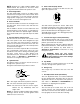
NE, R WARNING 15° N DO TTE D LI EPR ES ENT ING A 15 ° SL OPE Do not mow on inclines with a slope in excess of 15 degrees (a rise of approximately 2-1/2 feet every 10 feet). A riding mower could overturn and cause serious injury. If operating a walk-behind mower on such a slope, it is extremely difficult to maintain your footing and you could slip, resulting in serious injury. Operate RZT zero turn tractors across the face of slopes rather than up and down.
ENGINE MANUAL The Briggs & Stratton model 40757-0317-E1 engine is used on this RZT model tractor. The following section is a reproduction of the Briggs & Stratton engine manual that applies to the engine. Read this manual in its entirety. Observe all warnings and follow all operation and maintenance instructions provided in the manual.
MANUFACTURER’S LIMITED WARRANTY FOR: RESIDENTIAL USE ONLY COMMERCIAL USE VOIDS WARRANTY The limited warranty set forth below is given by Cub Cadet LLC with respect to new merchandise purchased and used in the United States, its possessions and territories.