Important Safe Operation Practices • Assembly & Set-Up • Controls & Operation • Product Care Operator’s Manual Zero-Turn Tractor Lapbar Table of Contents Important Safe Operation Practices...................... 2 Assembly & Set-Up................................................... 6 Controls & Operation............................................... 9 Product Care............................................................15 Parts/Warranty...............
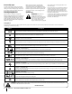
Important Safe Operation Practices 2 WARNING This symbol points out important safety instructions which, if not followed, could endanger the personal safety and/or property of yourself and others. Read and follow all instructions in this manual before attempting to operate this machine. Failure to comply with these instructions may result in personal injury. When you see this symbol.
Do: 2. 1. Mow across slopes, not up and down. Exercise extreme caution when changing direction on slopes. 2. Watch for holes, ruts, bumps, rocks, or other hidden objects. Uneven terrain could overturn the machine. Tall grass can hide obstacles. 3. Use slow speed. Choose a low enough speed so that you will not have to stop while on the slope. Avoid starting or stopping on a slope.
Do not modify engine To avoid serious injury or death, do not modify engine in any way. Tampering with the governor setting can lead to a runaway engine and cause it to operate at unsafe speeds. Never tamper with factory setting of engine governor. Notice Regarding Emissions When required, models are equipped with low permeation fuel lines and fuel tanks for evaporative emission control. California models may also include a carbon canister.
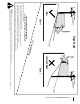
(OK) Figure 1 Slope Gauge ne d a s h e d li 15° Slope 15° USE THIS SLOPE GAUGE TO DETERMINE IF A SLOPE IS TOO STEEP FOR SAFE OPERATION! To check the slope, proceed as follows: 1. Remove this page and fold along the dashed line. 2. Locate a vertical object on or behind the slope (e.g. a pole, building, fence, tree, etc.) 3. Align either side of the slope gauge with the object (See Figure 1 and Figure 2 ). 4. Adjust gauge up or down until the left corner touches the slope (See Figure 1 and Figure 2). 5.
2 Assembly & Set-Up Thank You Thank you for purchasing this product. It was carefully engineered to provide excellent performance when properly operated and maintained. Please read this entire manual prior to operating the equipment. It instructs you how to safely and easily set up, operate and maintain your machine. Please be sure that you, and any other persons who will operate the machine, carefully follow the recommended safety practices at all times.
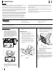
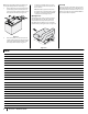
1. Remove the hex screws (a) and flat washers (b) from the hardware pack in your manual bag. See Figure 2-5. 3. Place the chute deflector on the deck, be sure to insert the tabs on the chute deflector into the holes on the deck. See Figure 2-6. 5 2. Make sure the deck is level, both front-toback and side-to-side. See the Product Care section for deck leveling information and instructions. 3.
Note: The positive battery terminal is marked Pos. (+). The negative battery terminal is marked Neg. (–). 1. Remove the plastic cover, if present, from the positive battery terminal and attach the red cable to the positive battery terminal (+) with the bolt (a) and hex nut (b). See Figure 2-9. 3. Position the red rubber boot (c) over the positive battery terminal to help protect it from corrosion.
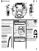
3 Controls & Operation (A) (E †) (A) (C) (B) (C) (B) (L) † (I) (E) (N) † (D) (L) † (M) † (K) (E †) (D) G (J) G (N) † (J) (K) (H) (H) (F) (F) † -- If Equipped Figure 3-1 Note: This Operator’s Manual covers several models. Tractor features may vary by model. Not all features in this manual are applicable to all tractor models and the tractor depicted may differ from yours.
Transmission Bypass Rods (F) Throttle Control (If equipped) The transmission bypass rods (one for each the RH and LH transmission) are located on the rear of the tractor, just inside each rear wheel. When engaged, the two rods open a bypass within the hydrostatic transmissions, which allows the tractor to be pushed short distances by hand. Refer to the Assembly & Set-Up section for instructions on using the bypass feature. When set in a given position, a uniform engine speed will be maintained.
Operation General Safety • • • • • • • • • • • • • • RECEIVE INSTRUCTION — Entirely read this operator’s manual. Learn to operate this machine SAFELY. Do not risk INJURY or DEATH. Allow only those who have become competent in its usage to operate this tractor. Before starting the engine or beginning operation, be familiar with the controls. The operator should be in the operator’s seat.
4. Note: Lap bars must be moved fully inward before pushing forward or backward to ensure brakes are fully disengaged. Parking the tractor on uneven terrain or a hill may cause the brakes to bind and not release fully. In this case the tractor will not drive when the lap bars are moved. If this happens, move the lap bar in the opposite direction slightly to take the load off the brakes and allow them to release fully.
Driving the Tractor In Reverse 2. WARNING To turn to the right while traveling in reverse, move the right drive control lever forward of the left drive control lever. See Figure 3-9. Always look behind and down on both sides of the tractor before backing up. Always look behind while traveling in the reverse direction. 1. Slowly and evenly move both drive control levers rearward. The tractor will start to move in the reverse direction. See Figure 3-7. 3.
Stopping the Tractor Note: When operating the tractor be certain that the throttle is always in the FAST position. Operating with the throttle at less than full throttle may lead to premature battery wear and a poor quality cut. 1. Move both drive control levers to the neutral position to stop the motion of the tractor. 2. Push the PTO downward to the OFF position. 3. Use the deck lift handle to raise the deck to its highest position. 3. 4.
4 Product Care Maintenance Schedule Before Each use Check Engine Oil Level Check & Clean Transmission Cooling Slots Check Air Filter for Dirty, Loose or Damaged Parts After First 5 Hours Every 10 Hours Every 25 Hours Every 50 Hours Every 100 Hours P P P P P P P P P Grease All Lubrication Points Check Intake Screen/Clean as Needed Check Blades/Sharpen or Replace as Needed Check Tire Pressure Check/Clean Underside of Deck P P P P P P P Inspect & Lube Deck Wheels Check Deck Level/Pitch P P P Check
Note: This Operator’s Manual covers several models. Tractor features may vary by model. Not all features in this manual are applicable to all tractor models and the tractor depicted may differ from yours. Troubleshooting 3. Place an appropriate oil collection container with at least a 2.5 quart capacity below the opening of the oil drain tube, to collect the used oil. Remove the oil fill cap/dipstick from the oil fill tube. 4.
Using the Deck Wash System General Battery Information WARNING WARNING When using the deck wash system, never engage the deck from any position other than the operator’s seat of the tractor. Do not use an assistant or engage deck in the presence of any bystanders. 1. Attach the nozzle adapter to a standard garden hose connected to a water supply. 2. Move the tractor to an area within reach of the hose where the dispersal of wet grass clippings is acceptable to you.
Removing The Tractor From Storage To adjust the drive control levers forward/ rearward, proceed as follows: 1. Check the engine oil. 2. Fully charge the battery and inflate the tires to the recommended pressure. 3. Fill the fuel tank with clean, fresh gasoline. 4. Start the engine and allow to idle for a few minutes to ensure engine is operating properly. 5. Drive the tractor without a load to make certain all the tractor systems are functioning properly.
Off-Season Storage Adjusting the Deck Wheels WARNING Keep hands and feet away from the discharge opening of the cutting deck. Note: The deck wheels are an anti-scalp feature of the deck and are not designed to support the weight of the cutting deck. The deck wheels should be approximately 1⁄4-1⁄2” above the ground when the deck is set in the desired height setting. To adjust the deck wheels see the Assembly & Set-Up section for instructions.
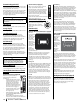
Charging the Battery 3. Remove the hex washer screw (a), flat washer (b) securing the belt keeper rod (c) to the transmission mount brackets (d) and remove the belt keeper rod (c). See Figure 4-11. Test and, if necessary, recharge the battery after the tractor has been stored for a period of time. • A voltmeter or load tester should read 12.6 volts (DC) or higher across the battery terminals. See Figure 4-10. Voltmeter Reading State of Charge Charging Time 12.7 100% Full Charge 12.4 75% 90 Min.
d. While still holding the PTO belt (a) downward, continue turning the PTO pulley (b) until the PTO belt (a) is rolled off the PTO pulley (b). Refer to Figure 4-16. (a) (b) (a) 9. Figure 4-16 e. Lower the deck into the lowest mowing position using the deck lift handle. See Figure 4-13. f. Move on to step 9. Pull the cotter pin (a) out of the front deck lift rod (b) securing it to the deck. See Figure 4-17. Slide the deck lift rod out of the front hanger bracket (c).
Note: Take note of the position of the belt guards (c) to ensure they are properly reinstalled. Note: On some decks it may be necessary to remove the spindle covers to remove and/or install the new belt. To remove the spindle covers, remove the screws securing them to the deck. 3. Carefully remove the belt from around the idler pulleys (a & b) and the spindle pulleys (d). 4. Install the new belt pulleys as shown and reinstall the belt covers. 5.
Notes 23
Notes