
Use and Care Manual


7Section 2 — ASSembly & Set-Up
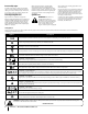
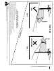
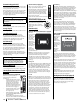
1. Remove the hex screws (a) and flat washers (b)
from the hardware pack in your manual bag.
See Figure 2-5.
(a)
(b)
(c)
(c)
(d)
Figure 2-5
2. Lift and swing that control lever (c) upward
until the slotted hole in the control lever (c)
bracket aligns with one of the holes in the
pivot bracket (d). See Figure 2-5.
3. Slide the flat washer (b) onto the hex screw
(a). From the outside, insert the hex screw
(a) with the flat washer (b) through the
control lever bracket (c) and the hole of the
pivot bracket (d). See Figure 2-5. Using a ⁄”
wrench snug the hex screw (a), but do not
fully tighten.
4. Note the relative position of the control
lever (c) to the pivot bracket (d), then repeat
the previous steps to reposition the other
control lever (c) in approximately the same
position.
Note: Torque the hex screws (a) down
tightly to prevent the control levers (c) from
slipping out of position.
5. Refer to “Adjusting the Drive Control Levers”
in the Product Care section for instructions
for the final adjustment of the levers.
Lower Deck Discharge Chute Deflector
WARNING
Never operate the mower deck without the chute deflector
installed and in the down position.
Note: For models with 34” Deck, skip ahead to
“Connecting the Battery Cables”. For models with a
46”, 50” and 54” Deck skip ahead to step 6.
1. Remove the keys that are attached with a
zip tie to the chute bracket.
2. Remove the flange lock nut and hex screw
from the deck.
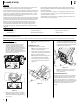
3. Place the chute deflector on the deck, be
sure to insert the tabs on the chute deflector
into the holes on the deck. See Figure 2-6.
3
4
5
5
4
Figure 2-6
4. When the tabs are installed in the deck,
slide the chute deflector toward the rear of
the tractor until the bolt hole in the chute
deflector aligns with the hole in the deck.
See Figure 2-6.
5. Secure the chute deflector in place with the
flange lock nut and hex screw removed in step
2. Tighten to 102-124 in-lbs. See Figure 2-6.
6. On models with a 46”, 50” and 54” decks
the chute is shipped attached and with a
stop bracket holding the chute upright. The
stop brackets must be removed prior to
operating the tractor.
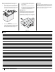
7. Holding the chute deflector fully upward,
remove the shipping brace. Lower the chute
deflector and discard the shipping brace.
See Figure 2-7.
Figure 2-7
Setting the Front Gauge Wheels
WARNING
Keep hands and feet away from the discharge opening of
the cutting deck.
Note: The deck wheels are an anti-scalp feature
of the deck and are not designed to support the
weight of the cutting deck.
Move the tractor on a firm and level surface,
preferably pavement, and proceed as follows:
1. Check the tire pressure, make sure the
pressure is correct and equal on all tires.
2. Make sure the deck is level, both front-to-
back and side-to-side. See the Product Care
section for deck leveling information and
instructions.
3. Select the height position of the cutting deck
by placing the deck lift lever in the normally
desired mowing height setting.
4. Check the wheels for contact or excessive
clearance with the surface below. The deck
wheels should have between ¼” and ½”
clearance above the ground. Proceed as
follows to adjust the wheels:
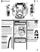
a. Remove the lock nut (a) securing
one of the front gauge wheel (b)
shoulder screws (c) to the deck.
Remove the gauge wheel (b) and
shoulder screw (c). See Figure 2-8.
(a)
(b)
(c)
Figure 2-8
b. Insert the shoulder screw into the
one of four index holes in the front
gauge wheel bracket that will give
the gauge wheel a ⁄⁄” clearance
with the ground.
c. Note the index hole of the just
adjusted wheel, and adjust the
other front gauge wheel into the
respective index hole of the other
front gauge wheel bracket.
Note: Refer to Adjusting the Deck in the
Product Care section of this manual for
more detailed instructions regarding
various deck adjustments.
Connecting the Battery Cables
WARNING
California
PROPOSITION 65 WARNING: Battery
posts, terminals, and related accessories contain lead and
lead compounds, chemicals known to the State of California
to cause cancer and reproductive harm. Wash hands after
handling.
CAUTION
When attaching battery cables, always connect the
POSITIVE (Red) wire to its terminal first, followed by the
NEGATIVE (Black) wire.
For shipping reasons, both battery cables on your
equipment may have been left disconnected from
the terminals at the factory. To connect the battery
cables, proceed as follows: