
Use and Care Manual


Controls & Operation
3
9
G
(B)
(L) †
(M) †
(D)
(H)
(N) †
(A)
(C)
(J)
(K)
(F)
(F)
(A)
(I)
† -- If Equipped
(B)
(C)
(N) †
(E)
(D)
(L) †
(K)
(J)
(E †)
(E †)
G
(H)
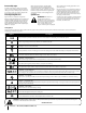
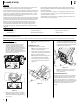
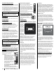
Figure 3-1
Note: This Operator’s Manual covers several
models. Tractor features may vary by model. Not
all features in this manual are applicable to all
tractor models and the tractor depicted may differ
from yours.
Note: References to LEFT, RIGHT, FRONT, and REAR
indicate that position on the tractor when facing
forward while seated in the operator’s seat.
RH & LH Drive Control Levers (A)
The RH and LH drive control levers are located on
each side of the operator’s seat. These hinged levers
pivot outward to open space to permit the operator
to either sit in the tractor seat, or to dismount
the tractor. The drive control levers must be fully
opened out and in the neutral position to start the
tractor engine. When the drive control levers are
fully outward, the parking brake is also engaged.
Each drive control lever controls the respective
transmission. Consequently, these levers control all of
the movements of the tractor. Driving and steering
utilizing these control levers is quite different from
conventional tractors, and will take some practice to
master. Refer to Operation for instructions on using
the drive control levers.
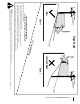
Deck Height Index (B)
The deck height index
consists of eight index
notches. Each notch
corresponds to a ⁄”
change in the deck height
position ranging from
1-⁄” at the lowest notch
to 4” at the highest notch.
Deck Lift Handle (C)
The deck lift handle is
used to raise and lower the
mower deck.
Pull the deck lift handle to
the left out of the index
notch and push downward
to lower the deck, or pull
upward to raise the deck.
When the desired height
is attained, move the deck
lift handle to the right until
fully in the index notch.
1
2
3
4
5
6
7
8
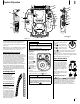
Ignition Module (D)
WARNING
Never leave a running machine unattended. Always
disengage PTO, set parking brake, stop engine and remove
key to prevent unintended starting.
Ignition Module w/ Reverse Caution Mode (If
equipped)
To start the
engine, insert
the key into
the ignition
switch and turn
clockwise to
the START
position. Release
the key into
the NORMAL
MOWING MODE
position
once the engine
has fired.
To stop the engine, turn the ignition key
counterclockwise to the STOP
position.
CAUTION
Prior to operating the riding mower, refer to both Safety
Interlock Switches and Starting The Engine in the Operation
section of this manual for detailed instructions regarding
the Ignition Switch Module and operating the riding mower
in REVERSE CAUTION MODE
.
Ignition Module (If equipped)
The ignition switch has three
positions:
STOP — The engine and
electrical system is turned off.
RUN — The riding mower
electrical system is energized.
START — The starter motor will turn over the
engine. Release the key immediately when the
engine starts
Note: To prevent accidental starting and/or battery
discharge, remove the key from the ignition switch
when the riding mower is not in use.
Power Take-Off (PTO) (E)
Electric PTO (If equipped)
The PTO switch operates the
electric PTO clutch mounted
on the bottom of the engine
crankshaft. Pull the switch
knob upward to engage the
PTO clutch, or push the knob
downward to disengage the
clutch.
The PTO switch must be in the
“OFF” position when starting
the engine.
Manual PTO (If equipped)
The PTO/blade engage handle is located on the
left pod. Activating the PTO engages power to
the cutting deck or other (separately available)
attachments. See the Operation section for
information and instructions on using the PTO.