
Use and Care Manual

10 Section 3— ASSembly & Set-Up
Position Drive Control levers
The drive control levers of the tractor are lowered for shipping
purposes. The hex screws and flat washers that normally secure
the control levers in their operating position are in a hardware
pack inside your manual bag. The control levers must be
repositioned to operate the tractor. To reposition the control
levers for operation, proceed as follows:
1. Remove the hex screws and flat washers from the hardware
pack in your manual bag.
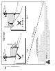
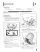
2. Lift and swing that control lever upward until the slotted
hole in the lever bracket aligns with one of the holes in the
pivot bracket. See Figure 3-4.
Control Lever
Hex Screw
Pivot
Bracket
Flat Washer
Figure 3-4
3. Slide the flat washer onto the hex screw. From the outside,
insert the hex screw with washer through the control lever
slot and the hole of the pivot bracket. See Figure 3-4. Using
a ⁄” wrench snug the screw, but do not fully tighten.
4. Note the relative position of the control lever to the pivot
bracket, then repeat the previous steps to reposition the
other control lever in approximately the same position.
CAUTION: Torque the screws down tightly to
prevent the control levers from slipping out of
position.
5. Refer to “Adjusting the Drive Control Levers” in the
Maintenance & Adjustments for instructions for the final
adjustment of the levers.
Lower Deck Discharge Chute Deflector
WARNING! Never operate the mower deck
without the chute deflector installed and in the
down position.
The discharge chute deflector must be installed before operating
the mower.
NOTE: For models with a 54” Deck skip ahead to step 4.
1. Remove the keys that are attached with a zip tie to the
chute bracket.
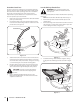
2. Remove the flange lock nuts from the deck. Do not remove
the push nuts or carriage bolts, leaving them in place will
aid in installing the chute. See Figure 3-5.
Figure 3-5
3. Install the discharge chute deflector using the carriage
bolts, push nuts and flange lock nuts as shown in Figure
3-6.
Figure 3-6