Safe Operation Practices • Set-Up • Operation • Maintenance • Service • Troubleshooting • Warranty Operator’s Manual RZT L Series Tractor WARNING READ AND FOLLOW ALL SAFETY RULES AND INSTRUCTIONS IN THIS MANUAL BEFORE ATTEMPTING TO OPERATE THIS MACHINE. FAILURE TO COMPLY WITH THESE INSTRUCTIONS MAY RESULT IN PERSONAL INJURY. CUB CADET LLC, P.O. BOX 361131 CLEVELAND, OHIO 44136-0019 Printed In USA Form No.
1 To The Owner Thank You Thank you for purchasing a Cub Cadet Zero-Turn Tractor. It was carefully engineered to provide excellent performance when properly operated and maintained. If applicable, the power testing information used to establish the power rating of the engine equipped on this machine can be found at www.opei.org or the engine manufacturer’s web site. Please read this entire manual prior to operating the equipment.
Important Safe Operation Practices 2 WARNING! This symbol points out important safety instructions which, if not followed, could endanger the personal safety and/or property of yourself and others. Read and follow all instructions in this manual before attempting to operate this machine. Failure to comply with these instructions may result in personal injury. When you see this symbol.
Do: 2. 1. Mow across slopes, not up and down. Exercise extreme caution when changing direction on slopes. 2. Watch for holes, ruts, bumps, rocks, or other hidden objects. Uneven terrain could overturn the machine. Tall grass can hide obstacles. 3. Use slow speed. Choose a low enough speed so that you will not have to stop while on the slope. Avoid starting or stopping on a slope.
Do not modify engine To avoid serious injury or death, do not modify engine in any way. Tampering with the governor setting can lead to a runaway engine and cause it to operate at unsafe speeds. Never tamper with factory setting of engine governor.
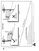
Section 2 — Important Safe Operation Practices Figure 1 line Figure 2 (TOO STEEP) 15° Slope WARNING! Slopes are a major factor related to tip-over and roll-over accidents which can result in severe injury or death. Do not operate machine on slopes in excess of 15 degrees. All slopes require extra caution. If you cannot back up the slope or if you feel uneasy on it, do not mow it. Always mow up and down slopes, never across the face of slopes. To check the slope, proceed as follows: 1.
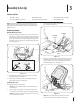
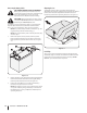
3 Assembly & Set-Up Contents of Crate • One RZT L Tractor • One Oil Drain Tube • One Deck Wash Hose Coupler • One Tractor Operator’s Manual • One Engine Operator’s Manual • One Hardware Pack NOTE: This Operator’s Manual covers several models. Tractor features may vary by model. Not all features in this manual are applicable to all tractor models and the tractor depicted may differ from yours. 2. Remove the two shoulder screws and lock nuts in the seat pan as shown in Figure 3-2.
Position Drive Control levers Lower Deck Discharge Chute Deflector WARNING! Never operate the mower deck without the chute deflector installed and in the down position. The drive control levers of the tractor are lowered for shipping purposes. The hex screws and flat washers that normally secure the control levers in their operating position are in a hardware pack inside your manual bag. The control levers must be repositioned to operate the tractor.
6. On models with a 46”, 50” and 54” decks the chute is shipped attached and with a stop bracket holding the chute upright. The stop brackets must be removed prior to operating the tractor. 7. Holding the chute deflector fully upward, remove the shipping brace. Lower the chute deflector and discard the shipping brace. See Figure 3-6. a. Remove the lock nut securing one of the front gauge wheel shoulder screws to the deck. Remove the gauge wheel and shoulder screw. See Figure 3-7.
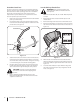
Connecting the Battery Cables CALIFORNIA PROPOSITION 65 WARNING! Battery posts, terminals, and related accessories contain lead and lead compounds, chemicals known to the State of California to cause cancer and reproductive harm. Wash hands after handling. Adjusting the Seat To adjust the position of the seat, pull up and hold the seat adjustment lever. Slide the seat forward or rearward to the desired position; then release the adjustment lever.
4 Controls & Features Deck Lift Handle LH Drive RH Drive Control Lever Control Lever Seat Adjustment Lever Deck Height Index Throttle Control or Throttle/Choke Control Hour Meter Choke Control PTO Switch Ignition Switch Module Cup Holder Fuel Level Window Fuel Tank Cap Storage Tray LH Transmission Bypass Rod NOTE: This Operator’s Manual covers several models. Tractor features may vary by model.
Ignition Switch Module Seat Adjustment Lever WARNING! Never leave a running machine unattended. Always disengage PTO, set parking brake, stop engine and remove key to prevent unintended starting. The seat adjustment lever is located below the front/left of the seat. The lever allows for adjustment forward or backward of the operator’s seat. Refer to the Assembly & Set-Up section for instructions on adjusting the seat position.
Hour Meter Low Battery LCD Service Minder & Hour Meter (If so equipped) At startup, the battery voltage is briefly displayed then changes to accumulated hours. The letters “LO” will display followed by the letters “BATT” and then followed by the meter’s accumulated time. “LO/BATT/TIME” is displayed on the LCD when the voltage drops below 11.5 volts. When this occurs, the battery is in need of a charge or the engine’s charging system is not generating sufficient amperage.
5 Operation General Safety • • RECEIVE INSTRUCTION — Entirely read this operator’s manual. Learn to operate this machine SAFELY. Do not risk INJURY or DEATH. Allow only those who have become competent in its usage to operate this tractor. Before starting the engine or beginning operation, be familiar with the controls. The operator should be in the operator’s seat. The PTO switch must be in the disengaged position and the RH and LH drive control levers moved fully outward in the neutral position.
Starting the Engine WARNING! This tractor is equipped with a safety interlock system designed for the protection of the operator. Do not operate the tractor if any part of the interlock system is malfunctioning. Periodically check the functions of the interlock system for proper operation. WARNING! For personal safety, the operator must be sitting in the tractor seat when starting the engine. 1.
Practice Operation (Initial Use) 3. Operating a zero-turn tractor is not like operating a conventional type riding tractor. Although and because a zero turn tractor is more maneuverable, getting used to operating the control levers takes some practice. NOTE: Although the tractor’s engine is designed to run at full throttle, when performing a practice session the tractor must be operated at less than full throttle. This only applies to practice.
Turning the Tractor While Driving Forward WARNING! When reversing the direction of travel, we recommend performing gradual ‘U’ turns where possible. Sharper turns increase the possibility of turf defacement, and could affect control of the tractor. ALWAYS slow the tractor before making sharp turns. To turn the tractor while driving forward, move the control levers as necessary so that one lever is rearward of the other. The tractor will turn in the direction of the rearward control lever. 1.
Turning While Driving Rearward To turn the tractor while driving rearward, move the control levers as necessary so that one lever is forward of the other. The tractor will turn in the direction of the forward control lever. 1. To turn to the left while traveling in reverse, move the left drive control lever forward of the right lever. See Figure 5-7. Reverse Caution Mode The REVERSE CAUTION MODE position of the key switch module allows the tractor to be operated in reverse with the blades (PTO) engaged.
Executing a Zero Turn Stopping the Tractor WARNING! When executing a zero turn, the tractor MUST BE STOPPED. Executing a zero turn while the tractor is moving can significantly reduce your control of the tractor and will cause severe turf defacement. 1. Stop the forward or reverse motion of the tractor by moving the two drive control levers to neutral. 2. To turn clockwise, move the left control lever forward while simultaneously moving the right control lever rearward. See Figure 5-10. 1.
Using the Mower Deck WARNING! Make certain the area to be mowed is free of debris, sticks, stones, wire or other objects that can be thrown by the rotating blades. NOTE: Do not engage the mower deck when lowered in grass. Premature wear and possible failure of the ‘V” belt and PTO clutch will result. Fully raise the deck or move to a non grassy area before engaging the mower deck. Periodically check the safety interlock circuits to ensure they are working properly.
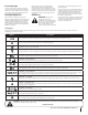
6 Maintenance & Adjustments Maintenance Schedule Before Each use Check & Clean Engine Cooling Fans for Debris Check Engine Oil Level Check Air Filter for Dirty, Loose or Damaged Parts After First 5 Hours Every 10 Hours Every 25 Hours Every 50 Hours P P P Prior to Storing See Engine Manual P P P P P P P Clean Battery Terminals Grease All Lubrication Points Check Intake Screen/Clean as Needed Check Blades/Sharpen or Replace as Needed Check Tire Pressure Check/Clean Underside of Deck P P P P P P P
NOTE: This Operator’s Manual covers several models. Tractor features may vary by model. Not all features in this manual are applicable to all tractor models and the tractor depicted may differ from yours. 5. After draining the oil, wipe any residual oil from the oil drain hose. Thread the square head plug into the drain hose fitting and fully tighten the plug. 6. Replace the oil filter, and refill the engine with new oil as instructed in the engine operator’s manual. 7.
3. Attach the hose coupler to the water port on the left of your deck surface. See Figure 6-2. Adjustments WARNING! Shut the engine off, remove the ignition key and engage the parking brake before making adjustments. Protect your hands by using heavy gloves when handling the blades. Adjusting RH & LH Drive Control Levers The RH and LH drive control levers can be adjusted up or down and forward or backward for the comfort of the operator.
Deck 1. NOTE: Check the tractor’s tire pressure before performing any deck leveling adjustments. Refer to Tires for information regarding tire pressure. Park the tractor on a firm, level surface and place the deck lift handle in a middle position. 2. Rotate the blade nearest the discharge chute so that it is parallel with the tractor. 3. Measure the distance from the front of the blade tip to the ground and the rear of the blade tip to the ground.
Drive Control Lever Stop Adjustment 3. When the drive control levers are both fully extended forward to the full-speed position and the tractor drifts left or right, the drive control lever stop adjustment can be adjusted to sync the wheel speeds. To perform the adjustment, proceed as follows: 1. Identify the side that the tractor is drifting to and adjust the opposite drive control lever. If the tractor drifts right, adjust the left control lever down (decrease speed) and vice versa. 2.
7 Service NOTE: This Operator’s Manual covers several models. Tractor features may vary by model. Not all features in this manual are applicable to all tractor models and the tractor depicted may differ from yours. WARNING! Before performing any service, place the PTO switch in the “OFF” position, engage the parking brake lever, turn the ignition key to the “OFF” position and remove the key from the switch.
Releasing Belt Tension with the Idler Pulley Rolling the Belt off the PTO Pulley 1. 1. Using the deck lift handle, raise the deck to the position that provides the most horizontal run of the belt between the deck idler pulleys and the PTO pulley on the bottom of the engine. 2. Sitting behind the tractor facing forward, reach beneath the tractor to grasp the belt at the front of the PTO pulley.
6. Pull the cotter pin out of the front deck lift rod securing it to the deck. See Figure 7-6. Slide the deck lift rod out of the front hanger bracket. Deck Installation Install the deck on the tractor as follows: 1. Place the deck lift handle in the highest mowing position See Figure 7-3. 2. Slide the deck under the tractor on the right side of the tractor lining up the deck hanger brackets and the deck lift arms.. 3.
Replacing the Belt 1. 2. 54” Decks Remove the deck from beneath the tractor, (refer to Deck Removal). Loosen, but do not remove the hardware on the right and left idler pulley. Refer to Figure 7-8 for 42” decks, Figure 7-9 for 46” decks and Figure 7-10 for 54” decks.
Mower Blade Care Changing the Transmission Drive Belt WARNING! Before performing any maintenance, place the PTO switch in the “OFF” position, engage the parking brake lever, turn the ignition key to the “OFF” position and remove the key from the switch. Protect your hands by using heavy gloves when handling the blades. When servicing the mower deck, be careful not to cut yourself on the sharpened blades. The cutting blades must be kept sharp at all times.
8 Troubleshooting Problem Excessive vibration Uneven cut Mower will not mulch grass (If Equipped w/Mulching Kit) Cause Remedy 1. Cutting blade loose or unbalanced. 1. Tighten blade and spindle. 2. Damaged or bent cutting blade. 2. Replace blade. 1. Deck not leveled properly. 1. Perform side-to-side deck adjustment. 2. Dull blade. 2. Sharpen or replace blade. 3. Uneven tire pressure. 3. Check tire pressure in all four tires. 1. Engine speed too low. 1.
9 Replacement Parts Component Part Number and Description 954-04033A 954-04325 954-04329A Deck Belt, RZT L42 Deck Belt, RZT L46 Deck Belt, RZT L54 954-04317A Drive Belt 942-04312 942-04244A 942-05056A Deck Blade, RZT L42 Deck Blade, RZT L46 Deck Blade, RZT L54 918-07087 918-05078A 918-06978 Deck Spindle, RZT L42 Deck Spindle, RZT L46 Deck Spindle, RZT L54 734-04155 Deck Wheel 925-1707D Battery 951-12179B 951-12426A Fuel Tank Cap (49-State models) Fuel Tank Cap (California models) 946-05145
Component Part Number and Description 946-05008 Brake Cable 631-05191A 631-05168A Discharge Chute Assy., RZT L42/46 Discharge Chute Assy., RZT L54 634-04293-0931 Wheel Assembly, RZT L42/46 634-04128-0931 Wheel Assembly, RZT L54 634-04212B Caster Wheel Assy., RZT L42 634-04711-0911 Caster Wheel Assy.
10 Attachments & Accessories The following attachments and accessories are compatible with your Cub Cadet RZT L tractor. See your Cub Cadet dealer or the retailer from which you purchased your tractor for information regarding price and availability.
Notes 11 35
Section 11— Notes
Section 11 — Notes 37
FEDERAL and/or CALIFORNIA EMISSION CONTROL WARRANTY STATEMENT YOUR WARRANTY RIGHTS AND OBLIGATIONS MTD Consumer Group Inc, the United States Environmental Protection Agency (EPA), and for those products certified for sale in the state of California, the California Air Resources Board (CARB) are pleased to explain the evaporative emission control system (ECS) warranty on your 2015-2016 small off-road equipment (outdoor equipment).
WARRANTED PARTS: The repair or replacement of any warranted part otherwise eligible for warranty coverage may be excluded from such warranty coverage if MTD Consumer Group Inc demonstrates that the outdoor equipment has been abused, neglected, or improperly maintained, and that such abuse, neglect, or improper maintenance was the direct cause of the need for repair or replacement of the part.
CUB CADET LLC MANUFACTURER’S LIMITED WARRANTY FOR RESIDENTIAL ZERO-TURN (“RZT”) MOWERS IMPORTANT: To obtain warranty coverage owner must present an original proof of purchase and applicable maintenance records to the servicing dealer. Please see the operator’s manual for information on required maintenance and service intervals.
Medidas importantes de seguridad • Configuración • Funcionamiento • Mantenimiento • Servicio • Solu Manual del Operador Tractor Serie RZT L ADVERTENCIA LEA Y RESPETE TODAS LAS NORMAS DE SEGURIDAD E INSTRUCCIONES INCLUIDAS EN ESTE MANUAL ANTES DE PONER EN FUNCIONAMIENTO ESTA MÁQUINA. SI NO RESPETA ESTAS INSTRUCCIONES PUEDE PROVOCAR LESIONES PERSONALES. CUB CADET LLC, P.O. BOX 361131 CLEVELAND, OHIO 44136-0019 Impreso en Estados Unidos de América Formulario No.
1 Al propietario Gracias Gracias por comprar una Cub Cadet cero a su vez de tractores. La misma ha sido diseñada cuidadosamente para brindar excelente rendimiento si se la opera y mantiene correctamente. Por favor lea todo este manual antes de operar el equipo. Le indica cómo configurar, operar y mantener la máquina con seguridad y fácilmente.
2 Medidas importantes de seguridad ADVERTENCIA: La presencia de este símbolo indica que se trata de instrucciones importantes de seguridad que se deben respetar para evitar poner en peligro su seguridad personal y/o material y la de otras personas. Lea y siga todas las instrucciones de este manual antes de poner en funcionamiento esta máquina. Si no respeta estas instrucciones puede provocar lesiones personales. Cuando vea este símbolo.
10. Esté atento a la cortadora y a la dirección de la descarga de los aditamentos y no apunte a nadie. Nunca haga funcionar la cortadora de césped sin que estén colocados la cubierta de descarga o todo el colector de recortes de césped. 11. No ponga las manos o los pies cerca de las piezas rotatorias o debajo de la plataforma de corte. El contacto con las cuchillas puede producir la amputación de manos y pies. 12.
No haga lo siguiente: Remolque 1. No gire en pendiente a menos que sea necesario; si lo hace, gire lentamente cuesta arriba y tenga sumo cuidado al girar. 1. Remolque únicamente con una máquina que cuente con un enganche diseñado para remolcar. No acople equipo remolcado excepto en el punto de enganche. 2. No corte el césped cerca de barrancas, zanjas o terraplenes.
k. Para reducir el riesgo de incendio, mantenga la máquina limpia de pasto, hojas y de acumulación de otros residuos. Limpie los derrames de aceite o combustible y saque todos los residuos embebidos en combustible. l. Nunca guarde la máquina o el recipiente de combustible en un espacio cerrado donde haya fuego, chispas o luz piloto, como por ejemplo de calentadores de agua, calefactores de ambientes, hornos, secadores de ropa u otros aparatos a gas. m.
Símbolos de seguridad En esta página se presentan y describen los símbolos de seguridad que pueden aparecer en este producto. Lea, entienda y cumpla todas las instrucciones incluidas en la máquina antes de intentar armarla y utilizarla. Symbol Description LEA LOS MANUALES DEL OPERADOR Lea, entienda y cumpla todas las instrucciones incluidas en los manuales antes de intentar armar la unidad y utilizarla. PELIGRO - GIRANDO HOJAS Nunca lleve pasajeros. Nunca transporte niños, aún con la cuchilla apagada.
8 Sección 2 — Medidas importantes de seguridad Figura 1 iscon tinua nea d 15° lí 15° Pendiente ADVERTENCIA! Las pendientes son un factor importante relacionado con un vuelco y renovación de los accidentes que pueden provocar lesiones graves o la muerte. No utilice la máquina en pendientes de más de 15 grados. Todos pendientes requiere mayor precaución. Si no puede retroceder en la pendiente o si se siente inseguro en ella, no la recorte. Siempre corte el césped en toda la superficie de la cuesta.
3 Montaje y Configuración Contenido del cajón • Un tractor corta césped • Un tubo de drenaje de aceite • Un Manual del operador del tractor RZT Manual • Un Manual del operador del motor NOTA: Este Manual abarca varios modelos. características del tractor pueden variar según el modelo. No todas las características de este manual son aplicables a todos los modelos de tractor y el tractor se muestra puede ser diferente de la suya. 2.
Posición palancas de control Las palancas de control del tractor se bajan para el embarque. Los tornillos hexagonales y las arandelas planas que normalmente fijan las palancas de control en su posición de trabajo se encuentran en un paquete de hardware dentro de su bolsa manual. Las palancas de control debe ser reposicionado para operar el tractor. Para cambiar la posición de las palancas de mando para la operación, proceda de la siguiente manera: 3.
7. Sosteniendo el deflector del canal hacia arriba por completo, quite la traba de seguridad. Baje el deflector del canal y deseche la traba de seguridad. Vea la Figura 3-6. a. Retire la tuerca de seguridad que fija uno de los tornillos de pivote de la rueda de calibre delanteros a la cubierta. Retire la rueda de calibración y el tornillo de hombro. Vea la Figura 6-6.
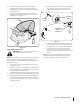
1. Retire la cubierta plástica, si es que está presente, del borne positivo de la batería y conecte el cable rojo al borne positivo de la batería (+) utilizando el perno y la tuerca hexagonal. Vea Figura 3-8. 2. Instale el soporte de enganche como se muestra en la Figura 3-10 y asegure con los tornillos de brida hexagonal y las tuercas de seguridad con brida que quitó en el paso 1. Figura 3-8 2.
4 Controles y Características Manija de elevación de la plataforma Posicionamiento de la altura de la plataforma Palanca de ajuste del asiento Palanca de control de transmisión izquierda Palanca de control de transmisión derecha Indicador de nivel de combustible Tapón del tanque de combustible Control del regulador o Del acelerador y del estrangulador Medidor horario Estrangulador Interruptor de potencia de arranque Interruptor de encendido Portacubeta Bandeja de almacenamiento LH varillas de deriv
Módulo Interruptor de encendido Bandeja de almacenamiento La bandeja de almacenamiento está ubicada en la parte posterior de la consola del lado derecho. ¡ADVERTENCIA! Palanca de ajuste del asiento Nunca deje la máquina en funcionamiento sin vigilancia. Siempre desconecte la toma de fuerza, el freno de mano, apague el motor y la llave para evitar el encendido accidental de quitar. La palanca de ajuste del asiento está ubicada debajo del asiento, adelante a la izquierda.
Servicio LCD Minder y cronómetro Batería Baja Cuando la llave de encendido se rota fuera de la posición de parada, pero no a la posición START, el Minder Servicio LCD y del cronómetro se disply brevemente el voltaje de la batería, seguido de horas acumuladas del tractor. En el arranque, el voltaje de la batería se visualiza brevemente a continuación, los cambios en las horas acumuladas. Las letras “LO” se mostrará seguido de las letras “BATT” y luego followedyby tiempo accumlulated del metro.
5 Funcionamiento Seguridad general • • RECIBA LAS INSTRUCCIONES - Lea este manual del operador en su totalidad. Aprenda a operar esta máquina CON SEGURIDAD. No se arriesgue a quedar expuesto a LESIONES o a la MUERTE. Solamente se debe permitir operar este tractor a quienes se hayan familiarizado a fondo con el uso del mismo. Antes de arrancar el motor o de empezar a operar, familiarícese con los controles. El operador debe estar en el asiento del operador.
Encendido del motor ¡ADVERTENCIA!: Esta unidad está equipada con un sistema de bloqueo de seguridad para protección del operador. No opere el tractor si alguna parte del sistema de bloqueo funciona mal. Controle periódicamente las funciones del sistema de bloqueo para verificar que funcionen adecuadamente. 6. 7. 8. ¡ADVERTENCIA!: Por razones de seguridad personal, el operador debe estar sentado en el asiento del tractor al arrancar el motor. 1.
Practique el modo de operación con el tractor (uso inicial) Operar un tractor con radio de giro cero no es lo mismo que operar un tractor convencional. Si bien precisamente un tractor con radio de giro cero es más maniobrable, es necesario practicar la operación de las palancas de control para acostumbrarse a las mismas. Recomendamos enfáticamente que encuentre un "área de práctica" de superficie razonable, nivelada y abierta, en la cual no haya obstrucciones, peatones ni mascotas.
Giro con el tractor en marcha directa ¡ADVERTENCIA! Al invertir la dirección del recorrido, le recomendamos que en lo posible realice giros graduales en "U". Los giros más agudos aumentan la posibilidad de que se deteriore el césped y podrían afectar el control del tractor. Conduzca SIEMPRE el tractor lentamente antes de girar en curvas cerradas. Para que el tractor gire mientras se desplaza hacia adelante, mueva las palancas de control según sea necesario para que una palanca quede más atrás que la otra.
Realizar un giro mientras se conduce marcha atrás Para que el tractor gire mientras se desplaza hacia atrás, mueva las palancas de control según sea necesario para que una palanca quede más adelante que la otra. El tractor girará en la dirección de la palanca que queda más adelante. 1. Para girar a la izquierda mientras se desplaza marcha atrás, mueva la palanca de control del lado izquierdo hacia adelante respecto de la palanca derecha. Vea la Figura 5-7.
6. El MODO DE PRECAUCIÓN EN MARCHA ATRÁS permanece activado hasta que: a. La clave se coloca ya sea en la posición de CORTE NORMAL o posición STOP o b. El operador se levanta del asiento. 3. Para girar en sentido contrario a las agujas del reloj, mueva la palanca de control del lado derecho hacia adelante mientras mueve simultáneamente la palanca de control izquierda hacia atrás. Vea la Figura 5-11. Giro de radio cero 1. 2.
Funcionamiento de PTO Accionar el embrague PTO de la siguiente manera: 1. Mueva la palanca de control del regulador aproximadamente a la posición de aceleración intermedia. 2. Tire del interruptor de la potencia de arranque (PTO) hacia arriba a la posición "ENGANCHADA". 3. Adelante la palanca del regulador a la velocidad operativa (velocidad máxima del motor). 4. El operador debe permanecer sentado en el tractor en todo momento.
6 Mantenimiento y Ajustes Programa de mantenimiento Antes de cada uso Revisar y Limpiar los ventiladores de enfriamiento del motor para Escombros Revise el nivel de aceite del motor Revise el filtro de aire para las piezas sucias, sueltas o dañadas Después de las primeras 5 horas Cada 10 Horas Cada 25 Horas Cada 50 Horas P P P Antes Consulte de el manual almacenar del motor P P P P P P P Terminales de la batería limpios Engrasar todos los puntos de lubricación Compruebe Rejilla de admisión/limpie
NOTA: Este manual de instrucciones abarca varios modelos. Características del tractor pueden variar según el modelo. No todas las funciones de este manual son aplicables a todos los modelos de tractor y el tractor se muestra puede diferir de la suya. ¡ADVERTENCIA! Antes de realizar cualquier operación Motor de mantenimiento o reparaciones, desconecte la toma de fuerza, el freno de mano, apague el motor y la llave para evitar el encendido accidental de quitar.
2. Desactive el PTO (enganche de cuchilla), ponga el freno de estacionamiento y pare el motor. 3. Enrosque el acople de manguera (embalado con el Manual del Operador de su tractor) en el extremo de la manguera de su jardín. 4. Una el acople de la manguera al puerto de agua a la izquierda de la superficie de la cubierta. Vea la Figura 6-2. Ajustes ¡ADVERTENCIA! Apague el motor, retire la llave de encendido y coloque el freno de mano antes de realizar ajustes.
Plataforma Nivelación de la plataforma (adelante atrás) NOTA: Controle la presión de neumáticos del tractor antes de realizar cualquier nivelación de la plataforma. Consulte la sección Neumáticos para obtener información sobre la presión de los neumáticos. NOTA: Controle la presión de neumáticos del tractor antes de realizar cualquier nivelación de la plataforma. Consulte la sección Neumáticos para obtener información sobre la presión de los neumáticos.
Almacenamiento del tractor Ruedas de plataforma ¡ADVERTENCIA! Mantenga las manos y los pies lejos de la abertura de descarga de la plataforma de corte. NOTA: Las ruedas de la plataforma son una característica anticuero cabelludo de la plataforma y no están diseñados para soportar el peso de la plataforma de corte. Las ruedas de la plataforma debe ser de aproximadamente 1⁄4-1⁄2” del suelo, cuando la cubierta se encuentra en el valor de altura deseado.
9. Lubricar todos los puntos de lubricación. 10. Jack el cortacésped y almacenarlo en los bloques para quitar el peso de los neumáticos. Extracción de la Segadora De Almacenamiento 28 1. Revise el aceite del motor. 2. Cargue completamente la batería, menor tractor cortacésped de bloques, e inflar los neumáticos a la presión recomendada. 3. Extraiga las bujías y límpielos. Usando el motor de arranque, arrancar el motor para bombear el exceso de aceite de los orificios de las bujías.
7 Servicio NOTA: Este manual de operación cubre distintos modelos. Las características del tractor pueden variar según los modelos. No todas las características en este manual se aplican a todos los modelos de tractor y la máquina que se ilustra aquí puede diferir de la suya. ¡ADVERTENCIA! Antes de realizar cualquier tarea Carga de la batería Si el tractor ha estado guardado durante un tiempo, pruebe la batería y, si es necesario, recárguela.
Para aflojar la tensión de la correa con la polea loca 1. Usando la manija de elevación de la plataforma, levante la plataforma a la posición que le ofrece mayor recorrido horizontal de la correa entre las poleas locas de la plataforma y la polea de la PTO en la base del motor. Vea la Figura 7-3. Haciendo rodar la correa para sacarla de la polea de la toma de fuerza (PTO) 1.
6. Tire del pasador de chaveta hacia afuera de la varilla de elevación delantera de la plataforma que la sujeta a la plataforma. Consulte la Figura 7-6. Deslice la varilla de elevación de la plataforma fuera de la ménsula de suspensión frontal. Instalación de la plataforma Instale la plataforma sobre el tractor de la siguiente forma: 1. Ubique la manija de elevación de la plataforma en la posición de corte más elevada. Vea la Figura 7-3. 2.
Cambio de la correa 1. 2. Cubierta 54” Retire la plataforma desde abajo del tractor, (consulte Extracción de la plataforma). Afloje, pero no quite el hardware de la derecha y la izquierda de la polea loca. Consulte la Figura 7-8 para 42“cubiertas, Figura 7-9 para 46” cubiertas y la Figura 7-10 para 54“cubiertas.
Cuidado de las cuchillas de la cortadora de césped ¡ADVERTENCIA! Antes de realizar cualquier tarea de mantenimiento, coloque el interruptor de la toma de fuerza (PTO) en la posición "OFF" (apagado), enganche la palanca del freno de mano, gire la llave de encendido a la posición "OFF" (apagado) y retire la llave del interruptor. Proteja sus manos utilizando guantes reforzados cuando manipule las cuchillas.
8 Solución de Problemas Problema Vibración excesiva Corte desigual La cortadora de césped no procesa los recortes como abono (si está equipada con kit de abono) 34 Causa Solución 1. Cuchilla de corte floja o descentrada. 1. Apriete la cuchilla y el husillo. 2. Cuchilla dañada o curvada. 2. Reemplace la cuchilla. 1. La plataforma no está correctamente nivelada. 1. Haga un ajuste de la plataforma de lado a lado. 2. La cuchilla de la cortadora no está afilada. 2. Afile o cambie la cuchilla. 3.
Notas 9 35
36 Section 9 — Notas
Section 9 — Notas 37
DECLARACIÓN FEDERAL y/o DE CALIFORNIA SOBRE GARANTÍAS EN EL CONTROL DE EMISIONES SUS DERECHOS Y OBLIGACIONES EN CUANTO A LA GARANTÍA MTD Consumer Group Inc, la Agencia de Protección Medioambiental de los Estados Unidos (EPA), y para aquellos productos certificados para su venta en el estado de California, el Departamento de los Recursos del Aire de California (CARB) se complacen en explicar la garantía que evaporativo sistema de control de emisiones (ECS) de su equipo (equipos de exteriores) de encendido po
8. Durante la totalidad del período de garantía del motor y equipo para todo terreno arriba mencionado, MTD Consumer Group Inc mantendrá un suministro de piezas bajo garantía suficiente para satisfacer la demanda esperada de tales piezas. 9. Cualquier pieza de reemplazo se podrá usar para el cumplimiento del mantenimiento o las reparaciones bajo garantía y se suministrarán sin cargo para el propietario. Dicho uso no reducirá las obligaciones de garantía de MTD Consumer Group Inc. 10.
GARANTÍA LIMITADA DEL FABRICANTE PARA CORTADORAS DE CÉSPED RESIDENCIALES DE RADIO DE GIRO CERO (“RZT”) IMPORTANTE: Para obtener cobertura de garantía, el propietario debe presentar una evidencia original de la compra y los registros de mantenimiento correspondientes al centro de servicio técnico autorizado del distribuidor. Consulte el manual del operador para obtener información sobre los intervalos de mantenimiento y servicio requeridos. LLC en P.O.