Safe Operation Practices • Set-Up • Operation • Maintenance • Service • Troubleshooting • Warranty Operator’s Manual RZT-S WARNING READ AND FOLLOW ALL SAFETY RULES AND INSTRUCTIONS IN THIS MANUAL BEFORE ATTEMPTING TO OPERATE THIS MACHINE. FAILURE TO COMPLY WITH THESE INSTRUCTIONS MAY RESULT IN PERSONAL INJURY. CUB CADET LLC, P.O. BOX 361131 CLEVELAND, OHIO 44136-0019 Printed In USA Form No.
1 To The Owner Thank You Thank you for purchasing a Cub Cadet Zero-Turn Tractor. It was carefully engineered to provide excellent performance when properly operated and maintained. If applicable, the power testing information used to establish the power rating of the engine equipped on this machine can be found at www.opei.org or the engine manufacturer’s web site. Please read this entire manual prior to operating the equipment.
Important Safe Operation Practices 2 WARNING! This symbol points out important safety instructions which, if not followed, could endanger the personal safety and/or property of yourself and others. Read and follow all instructions in this manual before attempting to operate this machine. Failure to comply with these instructions may result in personal injury. When you see this symbol.
12. A missing or damaged discharge cover can cause blade contact or thrown object injuries. 13. Stop the blade(s) when crossing gravel drives, walks, or roads and while not cutting grass. 14. Watch for traffic when operating near or crossing roadways. This machine is not intended for use on any public roadway. 15. Do not operate the machine while under the influence of alcohol or drugs. 16. Mow only in daylight or good artificial light. 17. Never carry passengers. 18. Back up slowly.
Children 1. Tragic accidents can occur if the operator is not alert to the presence of children. Children are often attracted to the machine and the mowing activity. They do not understand the dangers. Never assume that children will remain where you last saw them. a. b. c. d. e. f. g. 2. Service Safe Handling of Gasoline: 1. Keep children out of the mowing area and in watchful care of a responsible adult other than the operator. Be alert and turn machine off if a child enters the area.
3. 4. 5. 6 Periodically check to make sure the blades come to complete stop within approximately (5) five seconds after operating the blade disengagement control. If the blades do not stop within the this time frame, your machine should be serviced professionally by an authorized dealer. Regularly check the safety interlock system for proper function, as described later in this manual.
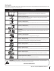
Safety Symbols This page depicts and describes safety symbols that may appear on this product. Read, understand, and follow all instructions on the machine before attempting to assemble and operate. Symbol Description READ THE OPERATOR’S MANUAL(S) Read, understand, and follow all instructions in the manual(s) before attempting to assemble and operate WARNING— ROTATING BLADES Do not put hands or feet near rotating parts or under the cutting deck. Contact with the blade(s) can amputate hands and feet.
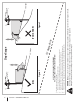
Section 2 — Safe Operation Practices Figure 1 line Figure 2 (TOO STEEP) 15° Slope WARNING! Slopes are a major factor related to tip-over and roll-over accidents which can result in severe injury or death. Do not operate machine on slopes in excess of 15 degrees. All slopes require extra caution. Always mow across the face of slopes, never up and down slopes. To check the slope, proceed as follows: 1. Remove this page and fold along the dashed line. 2.
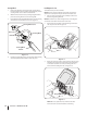
3 Assembly & Set-Up Contents of Crate • One Lawn Tractor • One Deck Wash Hose Coupler • One Engine Operator’s Manual • Two Hex Screws and Flat Washers • One Operator’s Manual Tractor Preparation Steering Wheel Column 1. The steering wheel column is tilted all the way back for shipping. Remove the upper crating material from the shipping pallet, and cut any bands or tie straps securing the tractor to the pallet. 2.
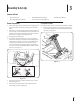
Steering Wheel Install Operator’s Seat 1. Remove the hardware for attaching the steering wheel from beneath the steering wheel cap. Carefully pry off the steering wheel cover to remove the hardware. To install the seat proceed as follows: 2. With the wheels of the tractor pointing straight forward, place the steering wheel over the steering shaft. 1. 3. Place the flat washer and belleville washer over the steering wheel and secure with the hex screw. See Figure 3-3.
Adjusting the Seat 3. To adjust the position of the seat, lift the seat adjustment lever up. Slide the seat forward or rearward to the desired position; then release the adjustment lever. Make sure seat is locked into position before operating the tractor. See Figure 3-6. Install the discharge chute deflector using the carriage bolts, push nuts and flange lock nuts as shown in Figure 3-8 and securely tighten the hardware.
Fuel Fill-Up Using a good grade of unleaded regular gasoline, fill the tank (beside the engine on the left side of the mower). When the fuel tank reaches one inch from the top of the tank, stop, DO NOT OVERFILL. Space must be left for expansion. Connecting the Battery Cables CALIFORNIA PROPOSITION 65 WARNING! Battery posts, terminals, and related accessories contain lead and lead compounds, chemicals known to the State of California to cause cancer and reproductive harm. Wash hands after handling.
4 Controls & Features Forward Drive Pedal Reverse Drive Pedal Parking Brake/Cruise Control Lever Brake Pedal Steering Wheel Deck Lift Handle Deck Height Index Seat Adjustment Lever Throttle/Choke Control PTO Knob LCD Service Minder & Hour Meter Cup Holder Ignition Switch Fuel Tank Cap Storage Tray Transmission Bypass Valves NOTE: References to LEFT, RIGHT, FRONT, and REAR indicate that position on the tractor when facing forward while seated in the operator’s seat.
PTO Knob Air Filter Service The PTO (Power Take-Off) knob is located on the RH console to the right of the operator’s seat. The letters “CLN” will display, followed by the letters “AIR”, followed by “FILT”, then followed by the meter’s accumulated time. “CLN/AIR/FILT/TIME” will alternate on the display for 7 minutes after the meter reachges 25 hours. This air filter service minder time interval will be every 25 hours.
Park Brake/ Cruise Control Lock Pedal The park brake/cruise control lock pedal is located at the base of the steering column. It is used to engage the park brake when the tractor is at rest. Engaging the lever while the tractor is in motion allows the tractor to remain at a constant ground speed without applying pressure to the forward drive pedal. Refer to the Operation section of this manual for detailed instructions regarding the parking brake as well as the cruise control feature.
5 Operation General Safety Before Operating Your Tractor • RECEIVE INSTRUCTION — Entirely read this operator’s manual. Learn to operate this machine SAFELY. Do not risk INJURY or DEATH. Allow only those who have become competent in its usage to operate this tractor. • Before you operate the tractor, study this manual carefully to familiarize yourself with the operation of all the instruments and controls. It has been prepared to help you operate and maintain your tractor efficiently.
Starting the Engine 6. WARNING! This tractor is equipped with a safety interlock system designed for the protection of the operator. Do not operate the tractor if any part of the system is malfunctioning. Periodically check the function of the interlock system for proper operation. WARNING! For personal safety, the operator must be sitting in the tractor seat when starting the engine.
Driving The Tractor 6. slowly push forward on the reverse drive pedal with the ball of your foot (NOT your heel) until the desired speed is achieved. See Figure 5-2. WARNING! Avoid sudden starts, excessive speed and sudden stops. 1. Release the parking brake. Move the throttle/choke control lever (if equipped) or the throttle (if equipped) into the FAST position. 2. To travel FORWARD, slowly press the forward drive pedal forward until the desired speed is achieved. See Figure 5-2.
Mowing Engaging the PTO WARNING! To help avoid blade contact or a thrown object injury, keep bystanders, helpers, children and pets at least 75 feet from the machine while it is in operation. Stop machine if anyone enters the area. The following information will be helpful when using the cutting deck with your tractor. WARNING! Plan your mowing pattern to avoid discharge of materials toward roads, sidewalks, bystanders and the like.
6 Maintenance & Adjustments Maintenance Schedule Before Each use Every 10 Hours P Clean Battery Terminals P Lube Front Caster Wheels and Wheel Spindles Check Engine Cooling Fins for Debris (Clean as Necessary) Every 25 Hours P P Lube Pedal Pivot Points P P P P P Grease Front Castings Maintenance Prior to Storing 3. If your engine has the oil drain valve setup shown if Figure 6-1, see the Oil Drain Valve section on page 21.
4. If your engine has the oil drain hose setup in Figure 6-2, see the Oil Drain Hose section below. Oil Fill Cap/Dipstick Oil Filler Oil Fill Tube Oil Drain Hose (If equipped) 1. Remove the hose from the retaining loop-clamp. Route the free end of the oil drain hose toward an appropriate oil collection container with at least a 2.5 quart capacity, to collect the used oil. Remove the oil fill cap/dipstick from the oil fill tube. 2.
Tractor Storage Removing The Tractor From Storage If your tractor is not going to be operated for an extended period of time (thirty days to approximately six months), the tractor should be prepared for storage. Store the tractor in a dry and protected location. If stored outside, cover the tractor (including the tires) to protect it from the elements. The procedures outlined below should be performed whenever the tractor is placed in storage. 1. Check the engine oil. 2.
4. Turn the water on. 5. While sitting in the operator’s position on the tractor, start the engine and place the throttle in the FAST position. See Figure 6-5. 6. Engage the PTO. 7. Remain in the operator’s position with the cutting deck engaged for a minimum of two minutes, allowing the underside of the cutting deck to thoroughly rinse. 8. Disengage the PTO. 9. Turn the ignition key to the STOP tractor’s engine off. 10.
Adjustments Leveling the Deck (Front-to-Rear) NOTE: Check the tractor’s tire pressure before performing any deck leveling adjustments. Refer to Tires above for information regarding tire pressure. NOTE: Check the tractor’s tire pressure before performing any deck leveling adjustments. Refer to Tires on page 22 for information regarding tire pressure. Always level the deck side to side before front to rear.
Setting the Deck Wheels Adjusting the Rollers (If so equipped) Move the tractor on a firm and level surface, preferably pavement, and proceed as follows To adjust the rollers proceed as follows: 1. Select the height position of the cutting deck by placing the deck lift handle in the normally desired mowing height setting. 2. Check the deck wheels for contact or excessive clearance with the surface below. The deck wheels should have between ¼-½” clearance above the ground. 3.
7 Service NOTE: This Operator’s Manual covers several models. Tractor features may vary by model. Not all features in this manual are applicable to all tractor models and the tractor depicted may differ from yours. WARNING! Before performing any service, place the PTO switch in the “OFF” position, engage the parking brake lever, turn the ignition key to the “OFF” position and remove the key from the switch.
Deck Removal 5. Remove the mower deck from the tractor as follows: 1. Move the tractor to a level surface, disengage the PTO, stop the engine, and set the parking brake. 2. Using the deck lift handle, raise the deck to the position that provides the most horizontal run of the belt between the deck idler pulleys and the PTO pulley on the bottom of the engine. See Figure 7-3. While still holding the belt downward, continue turning the PTO pulley until the belt rolls off the pulley. Refer to Figure 7-4.
8. Locate the LH and RH deck release pins on each side of the deck. Pull the release pins outward and release the deck from the LH and RH deck lift arms. See Figure 7-6. 10. Sitting behind the tractor, facing forward, make certain the belt is not twisted; then reach beneath the tractor to grasp the belt and pull it toward the PTO pulley. WARNING! Use caution to avoid pinching your fingers when rolling the belt onto the PTO pulley. Deck Lift Arm 11.
3. Remove the two idler pulleys by removing the hex screws and flange lock nuts that secure them to the deck and the idler arm. See Figure 7-8. Do not lose any of the hardware when removing the hex screw and flange lock nut. Hex Screw 46” Deck 1. Remove the deck from beneath the tractor, (refer to Deck Removal). 2. Remove the hex washer screws securing the belt covers to the deck. See Figure 7-9.
6. 7. Place the belt around the idler pulleys removed in step 3 with the “V” side facing in. Once in place, reinstall all the hardware and tighten the flange lock nut to secure the assembly. See Figure 7-10. Route the belt as shown in Figure 7-10 and then reinstall the deck. 50” & 54” Decks 4. Remove the belt from the spindle pulleys. 5. Install the new belt around the spindle pulleys as shown and reinstall the belt covers. See Figure 7-11. 6.
4. To reinstall the blades, reverse the above process and tighten nut to 70-90 lb. ft. NOTE: Add a small amount of multi-purpose grease to the bolt threads to avoid corrosion and galvanic action. 5. Reinstall the deck (refer to Deck Installation). WARNING!: Never mow with dull blades. Blades that are bent should be replaced. The cutting blades are sharp and can cause severe injury. Wrap the cutting surface of the blade with a rag to avoid injury. Changing the Spindle Assembly 1.
8 Troubleshooting Problem Excessive vibration Uneven cut Mower will not mulch grass (If Equipped w/Mulching Kit) 32 Cause Remedy 1. Cutting blade loose or unbalanced. 1. Tighten blade and spindle. 2. Damaged or bent cutting blade. 2. Replace blade. 1. Deck not leveled properly. 1. Perform side-to-side deck adjustment. 2. Dull blade. 2. Sharpen or replace blade. 3. Uneven tire pressure. 3. Check tire pressure in all four tires. 1. Engine speed too low. 1.
9 Replacement Parts Component Part Number and Description 954-04033A 954-04325 954-05008 954-04329 Deck Belt, RZT-S42 Deck Belt, RZT-S46 Deck Belt, RZT-S50 Deck Belt, RZT-S54 954-04317A Drive Belt 942-04312 942-04244A 942-04053C 942-04053-X 742-05056 2-in-1 Blade, RZT-S42 2-in-1 Blade, RZT-S46 2-in-1 Blade, RZT-S50 Xtreme Blade, RZT-S50 2-in-1 Blade, RZT-S54 918-04822A 918-05078 918-04125B 618-06978 Spindle Assembly, RZT-S42 Spindle Assembly, RZT-S46 Spindle Assembly, RZT-S50 Spindle Assembly, RZT-
Component 34 Section 9 — Replacement Parts Part Number and Description 625-05000 Ignition Key 631-04288 631-05162 Chute Deflector, RZT-S42 & RZT-S46 Chute Deflector, RZT-S50 & RZT-S54 634-04293 634-04128 Wheel Assembly, RZT-S42 Wheel Assembly, RZT-S46 & RZT-S50 634-04711 Caster Wheel Assembly
10 Attachments & Accessories Part No. Part 19B70020100 42” & 46” Bagger Kit 19B70004100 50” Bagger Kit 19A70043100 54” Bagger Kit 19A30006100 42” Mulch Kit 19A30005100 46” Mulch Kit 190-193-000 50” Mulch Kit 19A70042100 54” Mulch Kit 490-850-0005 Blade Removal Tool 490-850-0008 Oil Siphon 490-900-0045 Oil Filter Wrench 19A70025100 Hitch Kit 490-850-0005 Blade Removal Tool SPW-136 Spark Plug Wrench 490-325-0022 16 oz. Tire & Tube Sealant by Tire Science™ 490-325-0020 32 oz.
Notes 36 11
Section 11 — Notes 37
FEDERAL and/or CALIFORNIA EMISSION CONTROL WARRANTY STATEMENT YOUR WARRANTY RIGHTS AND OBLIGATIONS MTD Consumer Group Inc, the United States Environmental Protection Agency (EPA), and for those products certified for sale in the state of California, the California Air Resources Board (CARB) are pleased to explain the emission (evaporative and/or exhaust) control system (ECS) warranty on your 2013 and later small off-road spark-ignited engine and equipment (outdoor equipment engine).
10. Add-on or modified parts that are not exempted by the Air Resources Board may not be used. The use of any non-exempted add-on or modified parts by the ultimate purchaser will be grounds for disallowing a warranty claims. MTD Consumer Group Inc will not be liable to warrant failures of warranted parts caused by the use of a non-exempted add-on or modified part.
CUB CADET LLC MANUFACTURER’S LIMITED WARRANTY FOR RESIDENTIAL ZERO-TURN (“RZT”) MOWERS IMPORTANT: To obtain warranty coverage owner must present an original proof of purchase and applicable maintenance records to the servicing dealer. Please see the operator’s manual for information on required maintenance and service intervals.
Medidas importantes de seguridad • Configuración • Funcionamiento • Mantenimiento • Servicio • Solución de problemas • Garantía Manual del operador RZT-S ADVERTENCIA LEA Y SIGA TODAS LAS INSTRUCCIONES DE ESTE MANUAL ANTES DE PONER EN FUNCIONAMIENTO ESTA MÁQUINA. SI NO RESPETA ESTAS INSTRUCCIONES PUEDE PROVOCAR LESIONES PERSONALES. CUB CADET LLC, P.O. BOX 361131 CLEVELAND, OHIO 44136-0019 Impreso en Estados Unidos de América Formulario No.
1 Al propietario Gracias Gracias por la compra de una Cub Cadet de giro cero Tractor. La misma ha sido diseñada cuidadosamente para brindar excelente rendimiento si se la opera y mantiene correctamente. Por favor lea todo este manual antes de operar el equipo. Le indica cómo configurar, operar y mantener la máquina con seguridad y fácilmente.
2 Medidas importantes de seguridad ¡ADVERTENCIA! La presencia de este símbolo indica que se trata de instrucciones de seguridad importantes que se deben respetar para evitar poner en peligro su seguridad personal y/o material y la de otras personas. Lea y cumpla todas las instrucciones de este manual antes de intentar operar esta máquina. Si no respeta estas instrucciones puede causar lesiones personales. Cuando vea este símbolo.
4 Funcionamiento en pendientes 12. Una cubierta de descarga que falte o esté dañada puede provocar lesiones por contacto con la cuchilla o por objetos arrojados. 13. Detenga la(s) cuchilla(s) cuando cruce caminos de gravilla, senderos o caminos y cuando no esté cortando el césped. 14. Vigile el tránsito vehicular cuando esté operando cerca de caminos o en cruces. Esta máquina no debe utilizarse en la vía pública. 15. No opere esta máquina estando bajo los efectos del alcohol o de drogas. 16.
Niños 1. Pueden ocurrir accidentes trágicos si el operador no está atento a la presencia de niños. Por lo general, los niños se sienten atraídos por este tipo de máquinas y su funcionamiento. No entienden los riesgos ni los peligros. Nunca asuma que los niños permanecerán en el mismo lugar donde los vio por última vez. a. b. c. d. e. f. g. 2. Servicio Manejo seguro de la gasolina: 1.
4. 5. 6 Controle periódicamente el funcionamiento del sistema de bloqueo de seguridad, tal como se describe más adelante en este manual. Si el sistema de bloqueo de seguridad no funciona correctamente, solicite el servicio de mantenimiento profesional al distribuidor autorizado. Inspeccione los pernos de montaje de la(s) cuchilla(s) y del motor a intervalos frecuentes, para verificar que estén bien ajustados.
Símbolos de seguridad En esta página se presentan y describen los símbolos de seguridad que pueden aparecer en este producto. Lea, entienda y cumpla todas las instrucciones incluidas en la máquina antes de intentar armarla y utilizarla. Símbolo Descripción LEA LOS MANUALES DEL OPERADOR Lea, entienda y cumpla todas las instrucciones incluidas en los manuales antes de intentar armar la unidad y utilizarla.
8 Sección 2 — Medidas importantes de seguridad Figura 1 tinua iscon nea d 15° lí 15° Pendiente ADVERTENCIA! Las pendientes son un factor importante relacionado con un vuelco y renovación de los accidentes que pueden provocar lesiones graves o la muerte. No utilice la máquina en pendientes de más de 15 grados. Todos pendientes requiere mayor precaución. Si no puede retroceder en la pendiente o si se siente inseguro en ella, no la recorte. Siempre corte el césped en toda la superficie de la cuesta.
3 Montaje y Configuración Contenido del cajón • Un tractor corta césped • Un acoplador de manguera para lavado de plataforma • Un Manual de operación del motor • Dos tornillo hexagonal y dos arandela plana • Un Manual del operador Preparación del tractor Columna del volante 1. Retire el material de embalaje superior del pálet de embarque, y corte cualquier banda o tira que fije el tractor al pálet. La columna de la dirección se inclina totalmente hacia atrás para el embarque. 2.
Volante 2. 1. Retire los elementos de ferretería para fijar el volante que están debajo de la tapa del volante. Extraiga con cuidado la cubierta del volante mediante palanca para retirar los elementos de ferretería. 2. Con las ruedas del tractor mirando hacia adelante, coloque el volante sobre el eje de dirección. 3. Coloque la arandela plana y la arandela belleville por encima del volante y ajústela con el tornillo hexagonal. Consulte la Figura 3-3.
Ajuste del asiento 3. Para ajustar la posición del asiento, levante la palanca de ajuste del asiento. Deslice el asiento hacia adelante o hacia atrás a la posición deseada; luego suelte la palanca de ajuste. Asegúrese de que el asiento esté fijo en su posición antes de operar el tractor. Consulte la Figura 3-6. Instale el deflector del canal de descarga usando los pernos del carro, las tuercas a presión y las tuercas de seguridad con brida, como se indica en la Fig.
Conexión de los cables de la batería ADVERTENCIA PROPOSICIÓN 65 DE CALIFORNIA Los bornes de la batería y los accesorios afines contienen plomo y compuestos de plomo, sustancias químicas que según lo establecido por el Estado de California causan cáncer y daños en el sistema reproductivo. Lávese las manos después de estar en contacto con estos componentes.
4 Controles y Características Pedal de freno Pedal de la transmisión marcha adelante Pedal de la transmisión hacia atrás Freno de mano / palanca de control de crucero Volante Manija de elevación de la plataforma Posicionamiento de la altura de la plataforma Palanca de ajuste del asiento Control del acelerador/estrangulador Perilla de la toma de fuerza (PTO) Servicio LCD Minder y cronómetro Portacubeta Interruptor de encendido Tapón del depósito de combustible Bandeja de almacenamiento Válvulas de d
Perilla de la toma de fuerza (PTO) Batería Baja La perilla de la toma de fuerza (PTO) está ubicado en la consola del lado derecho, a la derecha del asiento del operador. En el arranque, el voltaje de la batería se visualiza brevemente a continuación, los cambios en las horas acumuladas. Las letras “LO” se mostrará seguido de las letras “BATT” y luego followedyby tiempo accumlulated del metro. “LO / BATT / TIME” se visualiza en la pantalla LCD cuando la tensión cae por debajo de 11,5 voltios.
Control del regulador (Si lo tiene) Pedal de la transmisión marcha adelante El control del regulador está ubicado en la consola del lado izquierdo, a la izquierda del asiento del operador. Cuando se lo coloca en cierta posición, se mantiene una velocidad de motor uniforme. El pedal de la transmisión marcha adelante está ubicado a la derecha del tractor, sobre el estribo. Presione el pedal de transmisión marcha adelante hacia adelante para que el tractor se mueva en esa dirección.
5 Funcionamiento 16 Seguridad general Antes de hacer funcionar el tractor • RECIBA LAS INSTRUCCIONES - Lea este manual del operador en su totalidad. Aprenda a usar esta máquina DE MANERA SEGURA. No se arriesgue a quedar expuesto a LESIONES o a la MUERTE. Solamente se debe permitir operar este tractor a quienes se hayan familiarizado a fondo con el uso del mismo.
Encendido del motor 6. ¡ADVERTENCIA! Esta unidad está equipada con un sistema de bloqueo de seguridad para protección del operador. No opere el tractor si alguna parte del sistema funciona mal. Controle periódicamente el funcionamiento del sistema de bloqueo para verificar que funcionen adecuadamente. ¡ADVERTENCIA! Por razones de seguridad personal, el operador debe estar sentado en el asiento del tractor al arrancar el motor.
4. Gire la llave de encendido a la posición STOP quite la llave del interruptor de encendido. (parada) y 6. NOTA: Siempre quite la llave del interruptor de encendido para evitar el arranque accidental o la descarga de la batería si el equipo queda sin supervisión. el pedal de transmisión marcha atrás con la parte anterior de la planta del pie (NO con el talón) hasta alcanzar la velocidad deseada. Consulte la Fig. 5-2.
Corte de césped ¡ADVERTENCIA! Para tratar de evitar el contacto con las cuchillas o una lesión por algún objeto que sea arrojado, mantenga a los observadores, a los ayudantes, niños y mascotas alejados al menos 25 metros de la máquina mientras está en funcionamiento. Detenga la máquina si alguien se acerca. La siguiente información será de utilidad cuando use la plataforma de corte con su tractor.
6 Mantenimiento y Ajustes Programa de mantenimiento Antes de cada uso Cada 10 horas Antes de almacenar P Limpie los bornes de la batería Lubrique las rueditas delanteras y los husillos de las ruedas Controle las aletas de refrigeración del motor para detectar la presencia de residuos (limpie según sea necesario) Cada 25 horas P P P Lubrique los puntos de pivote del pedal P Engrase las rueditas delanteras Mantenimiento ¡ADVERTENCIA! Antes de realizar tareas de P P P P 3.
4. Si su motor tiene la configuración de la manguera de drenaje de aceite en la Figura 6-2 , consulte la sección de manguera de drenaje de aceite debajo. 5. Reemplace el filtro de aceite y vuelva a llenar el motor con aceite nuevo según las instrucciones en el manual del operador del motor . Manguera de drenaje de aceite (en su caso ) 1. Retire la manguera de la retención de malla -clamp .
3. 4. La batería debe guardarse con carga completa. Una batería descargada se puede congelar más pronto que una batería cargada. Una batería con carga completa se guarda por más tiempo en temperaturas frías que en temperaturas altas. Vuelva a cargar la batería antes de volver a ponerla en servicio. Aun cuando el tractor pueda arrancar, el sistema de carga del motor tal vez no recargue totalmente la batería.
3. Una el acople de la manguera al puerto de agua que se encuentra a la izquierda en la superficie de la plataforma. Consulte la Figura 6-3. Acople de boquilla Lubricación ¡ADVERTENCIA! Antes de lubricar, reparar o inspeccionar, desconecte la toma de fuerza (PTO), ponga el freno de mano, pare el motor y retire la llave, para evitar el encendido accidental del motor. Las ruedas delanteras Cada uno de los ejes de las ruedas delanteras y llantas está equipado con accesorios de engrase. Vea la Figura 6-4.
Neumáticos ¡ADVERTENCIA! Nunca exceda la presión máxima de inflado que se indica en los laterales de los neumáticos. Consulte los laterales de las ruedas para conocer con exactitud la presión máxima en psi recomendada por el fabricante. No los infle en exceso. Una presión de neumáticos despareja podría hacer que la plataforma corte el césped en forma desigual. Ajustes NOTA: Controle la presión de neumáticos del tractor antes de realizar cualquier nivelación de la plataforma.
Ajuste de las ruedas de la plataforma Ajuste de los rodillos (Si así está equipado) Mueva el tractor a una superficie firme y nivelada, preferentemente sobre el pavimento, y realice lo siguiente. Para ajustar los rodillos proceder como sigue: 1. Seleccione la posición de altura de la plataforma de corte colocando el manija de elevación de la plataforma en la configuración de altura de corte deseada. 2.
7 Servicio NOTA: Este manual de operación cubre distintos modelos. Las características del tractor pueden variar según los modelos. No todas las características en este manual se aplican a todos los modelos de tractor y la máquina que se ilustra aquí puede diferir de la suya.
Retiro de la plataforma 5. Retire la plataforma de corte del tractor de la siguiente forma: 1. Desplace el tractor a una superficie nivelada, desconecte la PTO, pare el motor y ponga el freno de mano. 2. Usando la manija de elevación de la plataforma, levante la plataforma a la posición que le ofrece mayor recorrido horizontal de la correa entre las poleas locas de la plataforma y la polea de la potencia de arranque en la base del motor. Consulte la Figura 7-3.
8. Ubique los pasadores de liberación de la plataforma del lado izquierdo y del lado derecho que se encuentran a cada lado de la plataforma. Tire de los pasadores de liberación hacia afuera y suelte la plataforma de los brazos de elevación del lado derecho e izquierdo de la plataforma. Consulte la Figura 7-6. 8.
3. Extraiga las dos poleas locas, para lo cual debe retirar los tornillos de cabeza hexagonal y las tuercas de seguridad con brida que las sujetan a la plataforma y el brazo de polea loca. Consulte la Figura 7-8. No afloje ningún elemento de ferretería al sacar el tornillo de cabeza hexagonal y la tuerca de seguridad con brida. Tornillo hexagonal Tapa de la polea Cubierta 46” 1. Retire la plataforma desde abajo del tractor (consulte Retiro de la plataforma en la página 26).
6. 7. Coloque la correa alrededor de las poleas locas que extrajo en el paso 3 con el lado en “V” orientado hacia adentro. Una vez que todo esté en su lugar, vuelva a colocar los elementos de ferretería y ajuste la tuerca de seguridad con brida para sujetar el conjunto. Consulte la Figura 7-10. Coloque la correa como se indica en la Figura 7-10 y vuelva a instalar la plataforma. 4. Retire la correa de las poleas del husillo. 5.
4. Para volver a instalar las cuchillas, realice el proceso anterior de forma inversa y apriete la tuerca a 70-40.82 kg. ft. NOTA: Agregue una pequeña cantidad de grasa multiuso a las roscas del perno para evitar la corrosión y la acción galvánica. 5. Cambio del conjunto del husillo 1. Retire la plataforma desde abajo del tractor (consulte Retiro de la plataforma en la página 26). 2. Retire la correa de transmisión. (Vea Cambio de la correa) 3. Saque la cuchilla.
8 Solución de Problemas Problema Vibración excesiva Corte desigual La cortadora de césped no procesa los recortes como abono (si está equipada con kit de abono) Causa Solución 1. Cuchilla de corte floja o descentrada. 1. Apriete la cuchilla y el husillo. 2. Cuchilla dañada o doblada. 2. Reemplace la cuchilla. 1. La plataforma no está correctamente nivelada. 1. Haga un ajuste de la plataforma de lado a lado. 2. Cuchilla desafilada. 2. Afile o cambie la cuchilla. 3.
Notas 9 33
DECLARACIÓN FEDERAL y/o DE CALIFORNIA SOBRE GARANTÍAS EN EL CONTROL DE EMISIONES SUS DERECHOS Y OBLIGACIONES EN CUANTO A LA GARANTÍA MTD Consumer Group Inc, la Agencia de Protección Medioambiental de los Estados Unidos (EPA), y para aquellos productos certificados para su venta en el estado de California, el Departamento de los Recursos del Aire de California (CARB) se complacen en explicar la garantía que cubre al sistema de control (ECS) de emisiones (evaporativas y/o de escape) de su equipo y motor (moto
6. El propietario del motor de equipos de exteriores no deberá pagar el trabajo de diagnóstico directamente asociado con una pieza garantizada defectuosa en relación con las emisiones, siempre y cuando dicho trabajo de diagnóstico se realice en un centro cubierto por la garantía. 7. MTD Consumer Group Inc es responsable por daños causados a otros componentes de motores o equipos derivados de la falla bajo garantía de cualquier pieza garantizada. 8.
GARANTÍA LIMITADA DEL FABRICANTE PARA CORTADORAS DE CÉSPED RESIDENCIALES DE RADIO DE GIRO CERO (“RZT”) IMPORTANTE: Para obtener cobertura de garantía, el propietario debe presentar una evidencia original de la compra y los registros de mantenimiento correspondientes al centro de servicio técnico autorizado del distribuidor. Consulte el manual del operador para obtener información sobre los intervalos de mantenimiento y servicio requeridos. LLC en P.O.