Safe Operation Practices • Set-Up • Operation • Maintenance • Service • Troubleshooting • Warranty Operator’s Manual RZT S Series Tractor WARNING READ AND FOLLOW ALL SAFETY RULES AND INSTRUCTIONS IN THIS MANUAL BEFORE ATTEMPTING TO OPERATE THIS MACHINE. FAILURE TO COMPLY WITH THESE INSTRUCTIONS MAY RESULT IN PERSONAL INJURY. CUB CADET LLC, P.O. BOX 361131 CLEVELAND, OHIO 44136-0019 Printed In USA Form No.
1 To The Owner Thank You Thank you for purchasing a Cub Cadet Zero-Turn Tractor. It was carefully engineered to provide excellent performance when properly operated and maintained. If applicable, the power testing information used to establish the power rating of the engine equipped on this machine can be found at www.opei.org or the engine manufacturer’s web site. Please read this entire manual prior to operating the equipment.
Important Safe Operation Practices 2 WARNING! This symbol points out important safety instructions which, if not followed, could endanger the personal safety and/or property of yourself and others. Read and follow all instructions in this manual before attempting to operate this machine. Failure to comply with these instructions may result in personal injury. When you see this symbol.
12. A missing or damaged discharge cover can cause blade contact or thrown object injuries. 13. Stop the blade(s) when crossing gravel drives, walks, or roads and while not cutting grass. 14. Watch for traffic when operating near or crossing roadways. This machine is not intended for use on any public roadway. 15. Do not operate the machine while under the influence of alcohol or drugs. 16. Mow only in daylight or good artificial light. 17. Never carry passengers. 18. Back up slowly.
Children 1. Tragic accidents can occur if the operator is not alert to the presence of children. Children are often attracted to the machine and the mowing activity. They do not understand the dangers. Never assume that children will remain where you last saw them. a. b. c. d. e. f. g. 2. Service Safe Handling of Gasoline: 1. Keep children out of the mowing area and in watchful care of a responsible adult other than the operator. Be alert and turn machine off if a child enters the area.
3. 4. 5. Periodically check to make sure the blades come to complete stop within approximately (5) five seconds after operating the blade disengagement control. If the blades do not stop within the this time frame, your machine should be serviced professionally by an authorized dealer. Regularly check the safety interlock system for proper function, as described later in this manual.
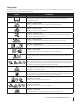
Safety Symbols This page depicts and describes safety symbols that may appear on this product. Read, understand, and follow all instructions on the machine before attempting to assemble and operate. Symbol Description READ THE OPERATOR’S MANUAL(S) Read, understand, and follow all instructions in the manual(s) before attempting to assemble and operate DANGER — ROTATING BLADES Never carry passengers. Never carry children, even with the blades off.
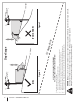
Section 2 — Safe Operation Practices Figure 1 line Figure 2 (TOO STEEP) 15° Slope WARNING! Slopes are a major factor related to tip-over and roll-over accidents which can result in severe injury or death. Do not operate machine on slopes in excess of 15 degrees. All slopes require extra caution. Always mow across the face of slopes, never up and down slopes. To check the slope, proceed as follows: 1. Remove this page and fold along the dashed line. 2.
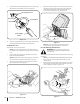
3 Assembly & Set-Up Contents of Crate • One Lawn Tractor • One Deck Wash Hose Coupler • One Engine Operator’s Manual • Two Hex Screws and Flat Washers • One Operator’s Manual Tractor Preparation Steering Wheel Column 1. The steering wheel column is tilted all the way back for shipping. Remove the upper crating material from the shipping pallet, and cut any bands or tie straps securing the tractor to the pallet. 2.
3. Place the flat washer and belleville washer over the steering wheel and secure with the hex screw. See Figure 3-3. 3. Rotate the seat into position and secure the seat into place with the previously removed shoulder screws and flange lock nuts. Be careful not to crimp or damage the wire harness while installing the seat. See Figure 3-5. Steering Wheel Cover Hex Screw Steering Wheel Belleville Washer Shoulder Screws Steering Wheel Column Flange Lock Nuts Figure 3-3 4.
3. Install the discharge chute deflector using the carriage bolts, push nuts and flange lock nuts as shown in Figure 3-7. Setting the Front Gauge Wheels WARNING! Keep hands and feet away from the discharge opening of the cutting deck. NOTE: The deck wheels are an anti-scalp feature of the deck and are not designed to support the weight of the cutting deck. Move the tractor on a firm and level surface, preferably pavement, and proceed as follows: Figure 3-7 4.
Connecting the Battery Cables CALIFORNIA PROPOSITION 65 WARNING! Battery posts, terminals, and related accessories contain lead and lead compounds, chemicals known to the State of California to cause cancer and reproductive harm. Wash hands after handling. Adjusting the Seat To adjust the position of the seat, lift the seat adjustment lever up. Slide the seat forward or rearward to the desired position; then release the adjustment lever. Make sure seat is locked into position before operating the tractor.
4 Controls & Features Brake Pedal Forward Drive Pedal Reverse Drive Pedal Parking Brake/Cruise Control Lever Steering Wheel Deck Lift Handle Deck Height Index Seat Adjustment Lever Throttle/Choke Control PTO Knob LCD Service Minder & Hour Meter Cup Holder Ignition Switch Module Storage Tray Fuel Tank Cap Transmission Bypass Valves NOTE: References to LEFT, RIGHT, FRONT, and REAR indicate that position on the tractor when facing forward while seated in the operator’s seat.
Ignition Switch Module Throttle/Choke Control WARNING! Never leave a running machine unattended. Always disengage PTO, set parking brake, stop engine and remove key to prevent unintended starting. The throttle/choke control is located on the RH console to the left of the hour meter/indicator panel. When set in a given position, a uniform engine speed will be maintained. To start the engine, insert the key into the ignition switch and turn clockwise to the START position.
Park Brake/ Cruise Control Lock Pedal CRUISE CONTROL The park brake/cruise control lock pedal is located at the base of the steering column. It is used to engage the park brake when the tractor is at rest. Engaging the lever while the tractor is in motion allows the tractor to remain at a constant ground speed without applying pressure to the forward drive pedal. Refer to the Operation section of this manual for detailed instructions regarding the parking brake as well as the cruise control feature.
5 Operation General Safety Before Operating Your Tractor • RECEIVE INSTRUCTION — Entirely read this operator’s manual. Learn to operate this machine SAFELY. Do not risk INJURY or DEATH. Allow only those who have become competent in its usage to operate this tractor. • Before you operate the tractor, study this manual carefully to familiarize yourself with the operation of all the instruments and controls. It has been prepared to help you operate and maintain your tractor efficiently.
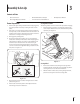
Starting the Engine 6. WARNING! This tractor is equipped with a safety interlock system designed for the protection of the operator. Do not operate the tractor if any part of the system is malfunctioning. Periodically check the function of the interlock system for proper operation. WARNING! For personal safety, the operator must be sitting in the tractor seat when starting the engine.
Driving The Tractor 6. slowly push forward on the reverse drive pedal with the ball of your foot (NOT your heel) until the desired speed is achieved. See Figure 5-2. WARNING! Avoid sudden starts, excessive speed and sudden stops. 1. Release the parking brake. Move the throttle/choke control lever into the FAST position. 2. To travel FORWARD, slowly press the forward drive pedal forward until the desired speed is achieved. See Figure 5-2.
3. Press the REVERSE PUSH BUTTON (Orange, Triangular Button) at the top, right corner of the key switch module. The red indicator light at the top, left corner of the key switch module will be ON while activated. See Figure 5-3. 4. Once activated (indicator light ON), the tractor can be driven in reverse with the cutting blades (PTO) engaged. 5. Always look down and behind before and while backing to make sure no children are around.
6 Maintenance & Adjustments Maintenance Schedule Before Each use Check & Clean Engine Cooling Fans for Debris Check Engine Oil Level Check Air Filter for Dirty, Loose or Damaged Parts After First 5 Hours Every 10 Hours Every 25 Hours Every 50 Hours Every 100 Hours P P P See Engine Manual P P P P P P P Clean Battery Terminals Grease All Lubrication Points Check Intake Screen/Clean as Needed Check Blades/Sharpen or Replace as Needed Check Tire Pressure Check/Clean Underside of Deck P P P P P P P P
NOTE: This Operator’s Manual covers several models. Tractor features may vary by model. Not all features in this manual are applicable to all tractor models and the tractor depicted may differ from yours. 5. After draining the oil, wipe any residual oil from the oil drain hose. Thread the square head plug into the drain hose fitting and fully tighten the plug. 6. Replace the oil filter, and refill the engine with new oil as instructed in the engine operator’s manual. 7.
4. Attach the hose coupler to the water port on the left of your deck surface. See Figure 6-2. Lubrication WARNING! Before lubricating, repairing, or inspecting, always disengage PTO, set parking brake, stop engine and remove key to prevent unintended starting. Front Wheels Each of the front wheel axles and rims is equipped with grease fittings. See Figure 6-3. Lubricate with a No. 2 multi-purpose grease applied with a grease gun after every 25 hours of tractor operation. Grease Fittings Figure 6-2 5.
Pivot Points & Linkage Leveling the Deck (Front-to-Rear) Lubricate all the pivot points on the drive system, parking brake and lift linkage at least once a season with light oil. Adjustments NOTE: Check the tractor’s tire pressure before performing any deck leveling adjustments. Refer to Tires on page 24 for information regarding tire pressure. Always level the deck side to side before front to rear. Deck The front of the deck should be between 1⁄4” and 3⁄8” lower than the rear of the deck.
Deck Wheels 4. NOTE: Use of a pressure washer or garden hose is not recommended to clean your riding mower. They may cause damage to electrical components, spindles, pulleys, bearings or the engine. The use of water will result in shortened life and reduce serviceability. WARNING!: Keep hands and feet away from the discharge opening of the cutting deck. NOTE: The deck wheels are an anti-scalp feature of the deck and are not designed to support the weight of the cutting deck.
7 Service NOTE: This Operator’s Manual covers several models. Tractor features may vary by model. Not all features in this manual are applicable to all tractor models and the tractor depicted may differ from yours. WARNING! Before performing any service, place the PTO switch in the “OFF” position, engage the parking brake lever, turn the ignition key to the “OFF” position and remove the key from the switch.
Releasing Belt Tension with the Idler Pulley Rolling the Belt off the PTO Pulley 1. 1. Using the deck lift handle, raise the deck to the position that provides the most horizontal run of the belt between the deck idler pulleys and the PTO pulley on the bottom of the engine. 2. Sitting behind the tractor facing forward, reach beneath the tractor to grasp the belt at the front of the PTO pulley.
6. Pull the cotter pin out of the front deck lift rod securing it to the deck. See Figure 7-6. Slide the deck lift rod out of the front hanger bracket. Deck Installation Install the deck on the tractor as follows: 1. Place the deck lift handle in the highest mowing position See Figure 7-3. 2. Slide the deck under the tractor on the right side of the tractor lining up the deck hanger brackets and the deck lift arms.. 3.
Replacing the Belt 1. 2. 54” Decks Remove the deck from beneath the tractor, (refer to Deck Removal). Loosen, but do not remove the hardware on the right and left idler pulley. Refer to Figure 7-8 for 42” decks, Figure 7-9 for 46” decks and Figure 7-10 for 54” decks.
Mower Blade Care Changing the Transmission Drive Belt WARNING! Before performing any maintenance, place the PTO switch in the “OFF” position, engage the parking brake lever, turn the ignition key to the “OFF” position and remove the key from the switch. Protect your hands by using heavy gloves when handling the blades. When servicing the mower deck, be careful not to cut yourself on the sharpened blades. The cutting blades must be kept sharp at all times.
8 Troubleshooting Problem Excessive vibration Uneven cut Mower will not mulch grass (If Equipped w/Mulching Kit) 30 Cause Remedy 1. Cutting blade loose or unbalanced. 1. Tighten blade and spindle. 2. Damaged or bent cutting blade. 2. Replace blade. 1. Deck not leveled properly. 1. Perform side-to-side deck adjustment. 2. Dull blade. 2. Sharpen or replace blade. 3. Uneven tire pressure. 3. Check tire pressure in all four tires. 1. Engine speed too low. 1.
9 Replacement Parts Component Part Number and Description 954-04033A 954-04325 954-04329A Deck Belt, RZT S42 Deck Belt, RZT S46 Deck Belt, RZT S54 954-04317A Drive Belt 942-04312 942-04244A 942-05056A 2-in-1 Blade, RZT S42 2-in-1 Blade, RZT S46 2-in-1 Blade, RZT S54 918-07087 918-05078A 918-06978 Spindle Assembly, RZT S42 Spindle Assembly, RZT S46 Spindle Assembly, RZT S54 734-04155 Deck Wheel 925-1707D Battery 951-12179B Gas Cap 946-05145 Throttle/Choke Control Cable 625-05000 Ignition K
Component Part Number and Description 631-05191A 631-05168A Chute Deflector, RZT S42 & RZT S46 Chute Deflector, RZT S50 & RZT S54 634-04293 634-04128 Wheel Assembly, RZT S42 & RZT S46 Wheel Assembly, RZT S50 634-04711-0911 Caster Wheel Assembly KH-12-050-01-S Oil Filter KH-12-132-02-S Spark Plug KH-25-050-22-S1 Fuel Filter (RZT S42/54) KH-24-050-13-S Fuel Filter (RZT S46) KH-32-083-09-S1 Air Filter & Pre-Cleaner 32 Section 9 — Replacement Parts
10 Attachments & Accessories Part No. Part 19B70020100 42” & 46” Bagger Kit 19A70043100 54” Bagger Kit 19A30006100 42” Mulch Kit 19A30005100 46” Mulch Kit 19A70042100 54” Mulch Kit 490-850-0005 Blade Removal Tool 490-850-0008 Oil Siphon 490-900-0045 Oil Filter Wrench 19A70025100 Hitch Kit 490-850-0005 Blade Removal Tool SPW-136 Spark Plug Wrench 490-325-0022 16 oz. Tire & Tube Sealant by Tire Science™ 490-325-0020 32 oz.
FEDERAL and/or CALIFORNIA EMISSION CONTROL WARRANTY STATEMENT YOUR WARRANTY RIGHTS AND OBLIGATIONS MTD Consumer Group Inc, the United States Environmental Protection Agency (EPA), and for those products certified for sale in the state of California, the California Air Resources Board (CARB) are pleased to explain the evaporative emission control system (ECS) warranty on your 2014-2015 small off-road equipment (outdoor equipment).
WARRANTED PARTS: The repair or replacement of any warranted part otherwise eligible for warranty coverage may be excluded from such warranty coverage if MTD Consumer Group Inc demonstrates that the outdoor equipment has been abused, neglected, or improperly maintained, and that such abuse, neglect, or improper maintenance was the direct cause of the need for repair or replacement of the part.
CUB CADET LLC MANUFACTURER’S LIMITED WARRANTY FOR RESIDENTIAL ZERO-TURN (“RZT”) MOWERS IMPORTANT: To obtain warranty coverage owner must present an original proof of purchase and applicable maintenance records to the servicing dealer. Please see the operator’s manual for information on required maintenance and service intervals.
Medidas importantes de seguridad • Configuración • Funcionamiento • Mantenimiento • Servicio • Solución de problemas • Garantía Manual del operador Tractor Serie RZT S ADVERTENCIA LEA Y SIGA TODAS LAS INSTRUCCIONES DE ESTE MANUAL ANTES DE PONER EN FUNCIONAMIENTO ESTA MÁQUINA. SI NO RESPETA ESTAS INSTRUCCIONES PUEDE PROVOCAR LESIONES PERSONALES. CUB CADET LLC, P.O. BOX 361131 CLEVELAND, OHIO 44136-0019 Impreso en Estados Unidos de América Formulario No.
1 Al propietario Gracias Gracias por la compra de una Cub Cadet de giro cero Tractor. La misma ha sido diseñada cuidadosamente para brindar excelente rendimiento si se la opera y mantiene correctamente. Por favor lea todo este manual antes de operar el equipo. Le indica cómo configurar, operar y mantener la máquina con seguridad y fácilmente.
2 Medidas importantes de seguridad ¡ADVERTENCIA! La presencia de este símbolo indica que se trata de instrucciones de seguridad importantes que se deben respetar para evitar poner en peligro su seguridad personal y/o material y la de otras personas. Lea y cumpla todas las instrucciones de este manual antes de intentar operar esta máquina. Si no respeta estas instrucciones puede causar lesiones personales. Cuando vea este símbolo.
4 Funcionamiento en pendientes 12. Una cubierta de descarga que falte o esté dañada puede provocar lesiones por contacto con la cuchilla o por objetos arrojados. 13. Detenga la(s) cuchilla(s) cuando cruce caminos de gravilla, senderos o caminos y cuando no esté cortando el césped. 14. Vigile el tránsito vehicular cuando esté operando cerca de caminos o en cruces. Esta máquina no debe utilizarse en la vía pública. 15. No opere esta máquina estando bajo los efectos del alcohol o de drogas. 16.
Niños 1. Pueden ocurrir accidentes trágicos si el operador no está atento a la presencia de niños. Por lo general, los niños se sienten atraídos por este tipo de máquinas y su funcionamiento. No entienden los riesgos ni los peligros. Nunca asuma que los niños permanecerán en el mismo lugar donde los vio por última vez. a. b. c. d. e. f. g. 2. Servicio Manejo seguro de la gasolina: 1.
4. 5. Controle periódicamente el funcionamiento del sistema de bloqueo de seguridad, tal como se describe más adelante en este manual. Si el sistema de bloqueo de seguridad no funciona correctamente, solicite el servicio de mantenimiento profesional al distribuidor autorizado. Inspeccione los pernos de montaje de la(s) cuchilla(s) y del motor a intervalos frecuentes, para verificar que estén bien ajustados.
Símbolos de seguridad En esta página se presentan y describen los símbolos de seguridad que pueden aparecer en este producto. Lea, entienda y cumpla todas las instrucciones incluidas en la máquina antes de intentar armarla y utilizarla. Symbol Description LEA LOS MANUALES DEL OPERADOR Lea, entienda y cumpla todas las instrucciones incluidas en los manuales antes de intentar armar la unidad y utilizarla. PELIGRO - GIRANDO HOJAS Nunca lleve pasajeros. Nunca transporte niños, aún con la cuchilla apagada.
8 Sección 2 — Medidas importantes de seguridad Figura 1 tinua iscon nea d 15° lí 15° Pendiente ADVERTENCIA! Las pendientes son un factor importante relacionado con un vuelco y renovación de los accidentes que pueden provocar lesiones graves o la muerte. No utilice la máquina en pendientes de más de 15 grados. Todos pendientes requiere mayor precaución. Si no puede retroceder en la pendiente o si se siente inseguro en ella, no la recorte. Siempre corte el césped en toda la superficie de la cuesta.
3 Montaje y Configuración Contenido del cajón • Un tractor corta césped • Un acoplador de manguera para lavado de plataforma • Un Manual de operación del motor • Dos tornillo hexagonal y dos arandela plana • Un Manual del operador Preparación del tractor Columna del volante 1. Retire el material de embalaje superior del pálet de embarque, y corte cualquier banda o tira que fije el tractor al pálet. La columna de la dirección se inclina totalmente hacia atrás para el embarque. 2.
3. Coloque la arandela plana y la arandela belleville por encima del volante y ajústela con el tornillo hexagonal. Consulte la Figura 3-3. 3. Gire el asiento en su posición y asegure el asiento en su lugar con los tornillos que quitó de los hombros y las tuercas de brida de bloqueo. Tenga cuidado de no doblar o dañar el mazo de cables durante la instalación del asiento. Vea la Figura 3-5.
3. Instale el deflector del canal de descarga usando los pernos del carro, las tuercas a presión y las tuercas de seguridad con brida, como se indica en la Figura 3-7 y sujete bien los elementos de ferretería. Ajuste de las ruedas de calibración frontales ¡ADVERTENCIA! Mantenga las manos y los pies lejos de la abertura de descarga de la plataforma de corte.
Conexión de los cables de la batería ADVERTENCIA PROPOSICIÓN 65 DE CALIFORNIA Los bornes de la batería y los accesorios afines contienen plomo y compuestos de plomo, sustancias químicas que según lo establecido por el Estado de California causan cáncer y daños en el sistema reproductivo. Lávese las manos después de estar en contacto con estos componentes.
4 Controles y Características Pedal de freno Pedal de la transmisión marcha adelante Pedal de la transmisión hacia atrás Freno de mano / palanca de control de crucero Volante Manija de elevación de la plataforma Palanca de ajuste del asiento Posicionamiento de la altura de la plataforma Control del acelerador/estrangulador Perilla de la toma de fuerza (PTO) Servicio LCD Minder y cronómetro Tapón del depósito de combustible Portacubeta Interruptor de encendido Bandeja de almacenamiento Válvulas de de
Para detener el motor, gire la llave de encendido en sentido contrario a las agujas del reloj hasta la posición STOP (DETENCIÓN). PRECAUCIÓN: Antes de operar el tractor, remítase a ambos interruptores de bloqueo de seguridad y Puesta en Marcha del Motor en la sección Funcionamiento de este manual para ver instrucciones detalladas del Módulo del Interruptor de Encendido y del funcionamiento del tractor en el MODO PRECAUCIÓN MARCHA ATRÁS .
Portacubeta Batería Baja El portacubeta está ubicado en la consola del lado derecho, a la derecha del asiento del operador. En el arranque, el voltaje de la batería se visualiza brevemente a continuación, los cambios en las horas acumuladas. Las letras “LO” se mostrará seguido de las letras “BATT” y luego followedyby tiempo accumlulated del metro. “LO / BATT / TIME” se visualiza en la pantalla LCD cuando la tensión cae por debajo de 11,5 voltios.
5 Funcionamiento 16 Seguridad general Antes de hacer funcionar el tractor • RECIBA LAS INSTRUCCIONES - Lea este manual del operador en su totalidad. Aprenda a usar esta máquina DE MANERA SEGURA. No se arriesgue a quedar expuesto a LESIONES o a la MUERTE. Solamente se debe permitir operar este tractor a quienes se hayan familiarizado a fondo con el uso del mismo.
Encendido del motor 6. ¡ADVERTENCIA! Esta unidad está equipada con un sistema de bloqueo de seguridad para protección del operador. No opere el tractor si alguna parte del sistema funciona mal. Controle periódicamente el funcionamiento del sistema de bloqueo para verificar que funcionen adecuadamente. ¡ADVERTENCIA! Por razones de seguridad personal, el operador debe estar sentado en el asiento del tractor al arrancar el motor.
4. Gire la llave de encendido a la posición STOP quite la llave del interruptor de encendido. (parada) y 6. NOTA: Siempre quite la llave del interruptor de encendido para evitar el arranque accidental o la descarga de la batería si el equipo queda sin supervisión. Para conducir marcha atrás, verifique que el área de atrás esté despejada.
3. Presione el BOTÓN DE MARCHA ATRÁS (botón triangular de color naranja) en la esquina superior derecha del módulo del interruptor de llave. La luz indicadora roja en la esquina superior izquierda del módulo del interruptor de llave se mantiene encendida (ON) mientras esté activado. Vea la Figura 5-3. 4. Una vez activado (con la luz indicadora encendida), el tractor podrá operar en marcha atrás con las cuchillas de corte (PTO – potencia de arranque) enganchadas. 5.
6 Mantenimiento y Ajustes Programa de mantenimiento Antes de cada uso Revisar y Limpiar los ventiladores de enfriamiento del motor para Escombros Revise el nivel de aceite del motor Revise el filtro de aire para las piezas sucias, sueltas o dañadas Después de las primeras 5 horas Cada 10 Horas Cada 25 Horas Cada 50 Horas Cada 100 Horas P P P P P P P P P P Terminales de la batería limpios Engrasar todos los puntos de lubricación Compruebe Rejilla de admisión/limpie si es necesario Compruebe Cuchill
NOTA: Este manual de instrucciones abarca varios modelos. Características del tractor pueden variar según el modelo. No todas las funciones de este manual son aplicables a todos los modelos de tractor y el tractor se muestra puede diferir de la suya. ¡ADVERTENCIA! Antes de realizar cualquier operación Motor de mantenimiento o reparaciones, desconecte la toma de fuerza, el freno de mano, apague el motor y la llave para evitar el encendido accidental de quitar.
2. Desactive el PTO (enganche de cuchilla), ponga el freno de estacionamiento y pare el motor. 3. Enrosque el acople de manguera (embalado con el Manual del Operador de su tractor) en el extremo de la manguera de su jardín. 4. Una el acople de la manguera al puerto de agua a la izquierda de la superficie de la cubierta. Vea la Figura 6-2.
Puntos de pivote y varillaje 5. Lubrique todos los puntos de pivote del sistema de accionamiento, freno de estacionamiento y el mecanismo de elevación de por lo menos una vez por temporada con aceite ligero. Ajustes La plataforma se encuentra correctamente nivelada cuando las dos mediciones desde las puntas de las cuchillas son iguales. Una vez alcanzado el ajuste necesario, vuelva a ajustar el perno de cabeza hexagonal de la ménsula frontal de suspensión izquierda de la plataforma.
Ruedas de plataforma 5. NOTA: El uso de una lavadora a presión o manguera de jardín no se recomienda para limpiar su cortadora de césped. Pueden causar daños a los componentes eléctricos, engranajes, poleas, rodamientos o el motor. El uso de agua acortará la vida útil y reducir el mantenimiento. ¡ADVERTENCIA! Mantenga las manos y los pies lejos de la abertura de descarga de la plataforma de corte.
7 Servicio NOTA: Este manual de operación cubre distintos modelos. Las características del tractor pueden variar según los modelos. No todas las características en este manual se aplican a todos los modelos de tractor y la máquina que se ilustra aquí puede diferir de la suya.
Retiro de la plataforma 5. Retire la plataforma de corte del tractor de la siguiente forma: 1. Desplace el tractor a una superficie nivelada, desconecte la PTO, pare el motor y ponga el freno de mano. 2. Usando la manija de elevación de la plataforma, levante la plataforma a la posición que le ofrece mayor recorrido horizontal de la correa entre las poleas locas de la plataforma y la polea de la potencia de arranque en la base del motor. Consulte la Figura 7-3.
8. Ubique los pasadores de liberación de la plataforma del lado izquierdo y del lado derecho que se encuentran a cada lado de la plataforma. Tire de los pasadores de liberación hacia afuera y suelte la plataforma de los brazos de elevación del lado derecho e izquierdo de la plataforma. Consulte la Figura 7-6. de transmisión, hacia la polea de la PTO en la base del motor. 8.
Cuidado de las cuchillas de la cortadora de césped Cubierta 46” ¡ADVERTENCIA! Proteja sus manos utilizando guantes reforzados cuando manipule las cuchillas. Cuando realice el mantenimiento de la plataforma de corte, tenga cuidado para no cortarse con las cuchillas filosas. Polea del husillo Protecciones de la correa Las cuchillas de corte deben estar siempre afiladas.
4. Para volver a instalar las cuchillas, realice el proceso anterior de forma inversa y apriete la tuerca a 70-40.82 kg. ft. NOTA: Agregue una pequeña cantidad de grasa multiuso a las roscas del perno para evitar la corrosión y la acción galvánica. 5. Reinstale la plataforma (consulte Instalación de la plataforma). ¡ADVERTENCIA! Nunca corte el césped con las cuchillas desafiladas. Si las cuchillas están dobladas es necesario cambiarlas. Las cuchillas de corte son filosas y pueden causar lesiones graves.
8 Solución de Problemas Problema Vibración excesiva Corte desigual La cortadora de césped no procesa los recortes como abono (si está equipada con kit de abono) Causa Solución 1. Cuchilla de corte floja o descentrada. 1. Apriete la cuchilla y el husillo. 2. Cuchilla dañada o doblada. 2. Reemplace la cuchilla. 1. La plataforma no está correctamente nivelada. 1. Haga un ajuste de la plataforma de lado a lado. 2. Cuchilla desafilada. 2. Afile o cambie la cuchilla. 3.
Notas 9 31
32 Section 9 — Notas
Section 9 — Notas 33
DECLARACIÓN FEDERAL y/o DE CALIFORNIA SOBRE GARANTÍAS EN EL CONTROL DE EMISIONES SUS DERECHOS Y OBLIGACIONES EN CUANTO A LA GARANTÍA MTD Consumer Group Inc, la Agencia de Protección Medioambiental de los Estados Unidos (EPA), y para aquellos productos certificados para su venta en el estado de California, el Departamento de los Recursos del Aire de California (CARB) se complacen en explicar la garantía que evaporativo sistema de control de emisiones (ECS) de su equipo (equipos de exteriores) de encendido po
8. Durante la totalidad del período de garantía del motor y equipo para todo terreno arriba mencionado, MTD Consumer Group Inc mantendrá un suministro de piezas bajo garantía suficiente para satisfacer la demanda esperada de tales piezas. 9. Cualquier pieza de reemplazo se podrá usar para el cumplimiento del mantenimiento o las reparaciones bajo garantía y se suministrarán sin cargo para el propietario. Dicho uso no reducirá las obligaciones de garantía de MTD Consumer Group Inc. 10.
GARANTÍA LIMITADA DEL FABRICANTE PARA CORTADORAS DE CÉSPED RESIDENCIALES DE RADIO DE GIRO CERO (“RZT”) IMPORTANTE: Para obtener cobertura de garantía, el propietario debe presentar una evidencia original de la compra y los registros de mantenimiento correspondientes al centro de servicio técnico autorizado del distribuidor. Consulte el manual del operador para obtener información sobre los intervalos de mantenimiento y servicio requeridos. LLC en P.O.