Important Safe Operation Practices • Assembly & Set-Up • Controls & Operation • Product Care Operator’s Manual Zero-Turn Tractor Steering Wheel Table of Contents Important Safe Operation Practices...................... 2 Assembly & Set-Up................................................... 7 Controls & Operation..............................................11 Product Care............................................................16 Parts/Warranty...............
Important Safe Operation Practices 2 WARNING This symbol points out important safety instructions which, if not followed, could endanger the personal safety and/or property of yourself and others. Read and follow all instructions in this manual before attempting to operate this machine. Failure to comply with these instructions may result in personal injury. When you see this symbol.
2. Watch for holes, ruts, bumps, rocks, or other hidden objects. Uneven terrain could overturn the machine. Tall grass can hide obstacles. 3. Use slow speed. Choose a low enough speed so that you will not have to stop while on the slope. Avoid starting or stopping on a slope. If the tires are unable to maintain traction, disengage the blades and proceed slowly and carefully straight down the slope. 4. 5. 6.
5. Check the blade(s) and engine mounting bolts at frequent intervals for proper tightness. Also, visually inspect blade(s) for damage (e.g., excessive wear, bent, cracked). Replace the blade(s) with the original equipment manufacturer’s (O.E.M.) blade(s) only, listed in this manual. “Use of parts which do not meet the original equipment specifications may lead to improper performance and compromise safety!” 6. Mower blades are sharp.
Safety Symbols This page depicts and describes safety symbols that may appear on this product. Read, understand, and follow all instructions on the machine before attempting to assemble and operate. Symbol Description READ THE OPERATOR’S MANUAL(S) Read, understand, and follow all instructions in the manual(s) before attempting to assemble and operate DANGER — ROTATING BLADES Never carry passengers. Never carry children, even with the blades off.
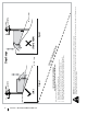
Section 2 — Important Safe Operation Practices Figure 1 20° (35%) Slope WARNING! Slopes are a major factor related to tip-over and roll-over accidents which can result in severe injury or death. Do not operate machine on slopes in excess of 15 degrees. All slopes require extra caution. If you cannot back up the slope or if you feel uneasy on it, do not mow it. Always mow up and down slopes, never across the face of slopes.
Assembly & Set-Up 2 Thank You Thank you for purchasing this product. It was carefully engineered to provide excellent performance when properly operated and maintained. Please read this entire manual prior to operating the equipment. It instructs you how to safely and easily set up, operate and maintain your machine. Please be sure that you, and any other persons who will operate the machine, carefully follow the recommended safety practices at all times.
3. Place the belleville washer (d) over the steering wheel (a) and secure with the hex screw (e). See Figure 2-7. 4. Place the steering wheel cover (b) over the center of the steering wheel (a) and push downward until it “clicks” into place. See Figure 2-7. Install Operator’s Seat Console Inside Cover There are two shipping methods for the seats, either the seat pan is attached to the seat or installed onto the tractor. Proceed with the instructions for your applicable model.
5. Secure the chute deflector in place with the flange lock nut and hex screw removed in step 2. Tighten to 102-124 in-lbs. See Figure 2-11. 6. On models with a 46”, 50” and 54” decks the chute is shipped attached and with a stop bracket holding the chute upright. The stop brackets must be removed prior to operating the tractor. 7. a. Remove the lock nut securing one of the front gauge wheel shoulder screws to the deck. Remove the gauge wheel and shoulder screw. See Figure 2-13.
Side Lever Adjust Knob Adjust Fuel Fill-Up To adjust the position of the seat, pull up and hold the seat adjustment lever. Slide the seat forward or rearward to the desired position; then release the adjustment lever. Make sure seat is locked into position before operating the tractor. See Figure 2-16. To adjust the position of the seat, rotate the seat forward and locate the clamp knobs (a) on the front of the seat pan. See Figure 2-17.
Controls & Operation 3 Standard Steering Column (O) (P) (R) (Q) (A) (C) (B) (I) (L) † (M) † (E) (N) † (K) (J) G (D) (T) † Tilt Steering Column † (U) † (Q) (O) (R) (S) † (P) Steering Wheel Not Shown for Clarity (H) (F) (F) † -- If Equipped Figure 3-1 Note: This Operator’s Manual covers several models. Tractor features may vary by model. Not all features in this manual are applicable to all tractor models and the tractor depicted may differ from yours.
Cup Holder (G) Throttle Control (If equipped) The cup holder is located toward the middle of the RH console. The throttle control is located on the RH console. When set in a given position, a uniform engine speed will be maintained. Storage Tray (H) The storage tray is located at the rear of the RH console. Seat Adjustment Lever (I) The seat adjustment lever is located under the seat. The seat adjustment lever allows for adjustment forward or backward of the operator’s seat.
Reverse Pedal (P) 12V Power Outlet (T) Before Operating Your Tractor The reverse drive pedal is located on the right side of the tractor along the running board. Ground speed is also controlled with the reverse drive pedal. The further downward the pedal is pivoted, the faster the tractor will travel. The pedal will return to its original position when it’s not pressed.
Starting the Engine 2. WARNING For personal safety, the operator must be sitting in the tractor seat when starting the engine. Note: Refer to the Engine Operator’s Manual for oil fill-up instructions and refer to the Assembly & Set-Up section for gasoline fill-up instructions. 1. Operator must be sitting in the tractor seat. 2. Engage the parking brake by pressing forward on the brake pedal (a), then press down on the parking break/cruise control lever (b) and then release the brake pedal (a).
Reverse Caution Mode (If equipped) The REVERSE CAUTION MODE position of the ignition module allows the tractor to be operated in reverse with the blades (PTO) engaged. Note: Mowing in reverse is not recommended. • Watch for holes, ruts, bumps, rocks, or other hidden objects. Uneven terrain could overturn the machine. Tall grass can hide obstacles. • Do not turn on slopes unless necessary; then turn slowly uphill and use extra care while turning.
4 Product Care Maintenance Schedule Before Each use Check/Clean Engine Intake Screens & Cooling Fans # Check/Clean Exhaust Manifold, Muffler Pipe & Muffler Shields # Check/Clean Top & Underside of Deck, Under and Around Spindle Covers & Belt Area # Check/Clean Around Fuses, Wiring and Wiring Harnesses # Check/Clean Around Transmission, Axle and Fans # Check Air Filter for Dirty, Loose or Damaged Parts Check Engine Oil Level After First 5 Hours Every 10 Hours Every 25 Hours Every 50 Hours P P P P P P
Note: This Operator’s Manual covers several models. Tractor features may vary by model. Not all features in this manual are applicable to all tractor models and the tractor depicted may differ from yours. Cleaning the Tractor Post-Operation Tractor Care After each operation of the tractor, the following procedures should be implemented to extend the life of your tractor and ensure safe operating conditions.
Maintenance Lubrication WARNING WARNING Before performing any maintenance or repairs, disengage the PTO, move the drive control levers fully outward in the neutral position engaging the parking brake, stop the engine and remove the key to prevent unintended starting. Engine Refer to the engine operator’s manual for all engine maintenance procedures and instructions.
Off-Season Tractor Storage If your tractor is not going to be operated for an extended period of time (thirty days to approximately six months), the tractor should be prepared for storage. Store the tractor in a dry and protected location. If stored outside, cover the tractor (including the tires) to protect it from the elements. The procedures outlined below should be performed whenever the tractor is placed in storage. 1.
Adjusting the Deck Wheels 4. Charging the Battery Keep hands and feet away from the discharge opening of the cutting deck. • A voltmeter or load tester should read 12.6 volts (DC) or higher across the battery terminals. See Figure 4-7. Note: The deck wheels are an anti-scalp feature of the deck and are not designed to support the weight of the cutting deck. The deck wheels should be approximately 1⁄4-1⁄2” above the ground when the deck is set in the desired height setting.
and downward while manually turning the PTO pulley to the right until the belt rides out onto the edge of the lower sheave of the pulley. Note: If pulling the right side of the belt, turn the pulley left. d. While still holding the PTO belt (a) downward, continue turning the PTO pulley (b) until the PTO belt (a) is rolled off the PTO pulley (b). Refer to Figure 4-10. 8. (a) 6. Figure 4-10 e. Lower the deck into the lowest mowing position using the deck lift handle. See Figure 4-8. f. Move on to step 6.
Tractor Blade Care 3. When reinstalling the blades, be sure they are installed so that the wings are pointing upward toward the top of the deck. Troubleshooting 4. Tighten the hex nuts (a) to 70-90 ft. lbs. 1. Cutting blade loose or unbalanced. 5. Reinstall the deck (refer to Deck Installation). 2. Damaged or bent cutting blade.
Notes 23
Notes