
Full Product Manual

20 Section 4 — Product care
Adjusting the Deck Wheels
WARNING
Keep hands and feet away from the discharge opening of
the cutting deck.
Note: The deck wheels are an anti-scalp feature
of the deck and are not designed to support the
weight of the cutting deck.
The deck wheels should be approximately ⁄⁄”
above the ground when the deck is set in the
desired height setting. To adjust the deck wheels
see the Assembly & Set-Up section for instructions.
Adjusting the Tilt Steering Column
If the steering column feels loose when it is adjusted
or is not adjusting properly, take the tractor to an
authorized service dealer to have it adjusted.
Service
Battery Removal
WARNING
Battery posts, terminals and related accessories contain
lead and lead compounds. Wash hands after handling.
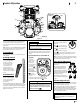
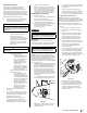
The battery is located beneath the seat frame. To
remove the battery:
1. Remove the hex washer screw (a) securing the
battery hold-down bracket (b) to the frame.
Then flip the battery hold-down bracket (b)
up to free the battery. See Figure 4-6.
(a)
(b)
Figure 4-6
2. Remove the hex cap screw and sems nut
securing the black negative battery lead
to the negative battery post (marked NEG).
Move the cable away from the negative
battery post.
3. Remove the hex cap screw and sems nut
securing the red positive battery lead to the
positive battery post (marked POS).
4. Carefully lift the battery out of the tractor.
5. Install the battery by repeating the above
steps in the reverse order.
WARNING
Always connect the positive lead to the battery before
connecting the negative lead. This will prevent sparking
or possible injury from an electrical short caused by
contacting the tractor body with tools being used to
connect the cables.
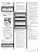
Charging the Battery
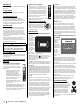
Test and, if necessary, recharge the battery after
the tractor has been stored for a period of time.
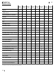
• A voltmeter or load tester should read
12.6 volts (DC) or higher across the battery
terminals. See Figure 4-7.
Voltmeter
Reading
State of
Charge
Charging
Time
12.7 100% Full Charge
12.4 75% 90 Min.
12.2 50% 180 Min.
12.0 25% 280 Min.
Figure 4-7
• Charge the battery with a 12-volt battery
charger at a MAXIMUM rate of 10 amps.
Servicing Electrical System
A fuse is installed to protect the tractor’s electrical
system from damage caused by excessive
amperage. Always use the same capacity fuse
for replacement. If the electrical system does not
function, check for a blown fuse.
If you have a recurring problem with blown fuses,
have the tractor’s electrical system checked by your
authorized service dealer.
Relays and Switches
There are several safety switches in the electrical
system. If a function of the safety interlock system
described earlier is not functioning properly, have
the electrical system checked by your authorized
service dealer.
Parking Brake Adjustment
If the tractor does not come to a complete stop
when the control levers are moved fully outward
engaging the parking brake, or if the tractor’s rear
wheels can roll with the parking brake engaged
(and the hydrostatic relief valve open), the brake is
in need of adjustment. See your authorized service
dealer to have the brake adjusted.
Deck Removal
Remove the tractor deck from the tractor as follows:
1. Move the tractor to a level surface,
disengage the PTO, stop the engine place
the control levers in the neutral/parking
brake engaged position.
2. Move the deck gauge wheels or rollers to
their highest setting (lowest deck setting).
3. Remove the ‘V’ belt from the PTO pulley,
located on the bottom of the engine, using one
of the following two methods.
WARNING
The muffler at the rear of the tractor may be extremely hot,
and could cause serious burns. Use extreme caution when
near the muffler. Allow the muffler to fully cool before
removing the belt from the PTO pulley.
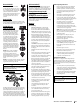
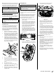
4. Releasing belt tension with the idler pulley:
a. Using the deck lift handle, raise the
deck to the position that provides
the most horizontal run of the belt
between the deck idler pulleys and
the PTO pulley on the bottom of the
engine. See Figure 4-8.
Lowest Mowing
Position
Highest Mowing
Position
Deck Lift
Handle
Figure 4-8
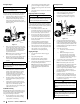
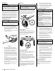
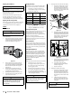
b. Working from the middle of the tractor,
pivot the idler bracket (a) and movable
idler pulley (b) rearward away from the
backside of the ‘V” belt just far enough
to lift the belt up and over the idler
pulley (b). See Figure 4-9.
46/54” Decks
42” Decks
(a)
(a)
(b)
(b)
Figure 4-9
c. From beneath the rear of the tractor,
slide the belt off of the PTO pulley on
the bottom of the engine.
d. Lower the deck into the lowest
mowing position using the deck lift
handle. See Figure 4-8.
e. Skip ahead to step 6.
5. Rolling the belt off the PTO pulley:
a. Using the deck lift handle, raise the
deck to the position that provides
the most horizontal run of the belt
between the deck idler pulleys and
the PTO pulley on the bottom of the
engine.
b. Sitting behind the tractor facing
forward, reach beneath the tractor
to grasp the belt at the front of the
PTO pulley.
WARNING
Use caution to avoid pinching your fingers when rolling the
belt off the PTO pulley.
c. Pull the left side of the belt rearward