
Full Product Manual


21Section 4 — Product care
and downward while manually
turning the PTO pulley to the right
until the belt rides out onto the edge
of the lower sheave of the pulley.
Note: If pulling the right side of the belt, turn
the pulley left.
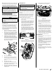
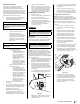
d. While still holding the PTO belt (a)
downward, continue turning the
PTO pulley (b) until the PTO belt (a) is
rolled off the PTO pulley (b). Refer to
Figure 4-10.
(a)
(b)
(a)
Figure 4-10
e. Lower the deck into the lowest
mowing position using the deck lift
handle. See Figure 4-8.
f. Move on to step 6.
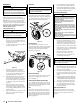
6. Pull the cotter pin (a) out of the front deck
lift rod (b) securing it to the deck. See Figure
4-11. Slide the deck lift rod out of the front
hanger bracket (c).
(a)
(b)
(c)
Figure 4-11
7. Locate the LH and RH deck release pins (a) on
each side of the deck. Pull the deck release
pins (a) outward and release the deck from the
LH and RH deck lift arms (b). See Figure 4-12.
(a)
(b)
Figure 4-12
8. Place the deck lift handle into the highest
mowing position and slide the deck out
from beneath the tractor. See Figure 4-8.
Deck Installation
Install the deck on the tractor as follows:
1. Place the deck lift handle in the highest
mowing position See Figure 4-8.
2. Slide the deck under the tractor on the right
side of the tractor lining up the deck hanger
brackets and the deck lift arms.
3. Once the deck is under the tractor, move the
deck lift handle to the lowest mowing position.
Note: To line the brackets up properly, it may be
necessary to place a small block of wood under
each side of the deck.
4. Pull the deck release pins outward and
maneuver the deck as necessary to align
the holes in the deck lift arms with the pins.
Refer to Figure 4-12.
5. When aligned, push each pin fully inward
through the lift arms to secure the arms in
the rear hanger bracket slots.
6. Reinstall the front deck lift rod and secure in
place with the cotter pin. Refer to Figure 4-11.
7. Make certain the ‘V’ belt is in the spindle
pulleys on the deck; then route the belt
rearward beneath the tractor frame, above
the transmission tube(s), to the PTO pulley
on the bottom of the engine.
8. Using the deck lift handle, raise the deck
to the position that provides the most
horizontal run of the belt between the deck
idler pulleys and the PTO pulley on the
bottom of the engine.
9. Make certain the belt is in the spindle
pulleys of the deck, and that the backside
of the belt is against both the fixed and
movable idler pulleys.
10. Sitting behind the tractor, facing forward,
make certain the belt is not twisted; then
reach beneath the tractor to grasp the belt
and pull it toward the PTO pulley.
WARNING
Use caution to avoid pinching your fingers when rolling the
belt onto the PTO pulley.
11. Pull the right side of the PTO belt rearward
and place the narrow V-side of the PTO belt
into the PTO pulley. See Figure 4-10.
12. While holding the PTO belt and PTO pulley
together, rotate the PTO pulley to the left (See
Figure 4-10). Continue holding and rotating
the PTO pulley and PTO belt until the PTO belt
is fully rolled into the PTO pulley.
Note: Before using the tractor double-check
the belt routing to make sure that the belt
has been routed properly.
Replacing the Belt
1. Remove the deck from beneath the tractor,
(refer to Deck Removal).
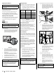
2. Loosen, but do not remove the hardware on
the right (a) and left idler pulley (b). Refer to
Figure 4-13 for 42” decks, Figure 4-14 for 46”
decks and Figure 4-15 for 50" & 54” decks.
42” Decks
(a)
(b)
(c)
(c)
(d)
(d)
(e)
Figure 4-13
46” Decks
(a)
(b)
(c)
(c)
(e)
(e)
Figure 4-14
50" & 54” Decks
(a)
(b)
(c)
(c)
(e)
(e)
Figure 4-15
Note: Take note of the position of the belt
guards (c) to ensure they are properly re-
installed.
Note: On some decks it may be necessary
to remove the spindle covers (d) to remove
and/or install the new belt. To remove
the spindle covers (d), remove the screws
securing them to the deck.
3. Carefully remove the belt from around the
idler pulleys (e) and the spindle pulleys (d).
4. Install the new belt pulleys as shown and
reinstall the belt covers.
5. Place the belt around the idler pulleys
removed in step 3 with the “V” side facing
in. Once in place, reinstall all the hardware
and tighten the flange lock nut to secure the
assembly.
6. Route the belt as shown and then reinstall
the deck (refer to Deck Installation)