
Full Product Manual


Assembly & Set-Up 2
7
Note: This Operator’s Manual covers several models. Tractor features may vary by model. Not all features in this manual are applicable to all tractor models and the
tractor depicted may differ from yours.
Note: All references in this manual to the left or right side and front or back of the tractor are from the operating position only. Exceptions, if any, will be specified.
Thank you for purchasing this product. It was carefully engineered to provide
excellent performance when properly operated and maintained.
Please read this entire manual prior to operating the equipment. It instructs you
how to safely and easily set up, operate and maintain your machine. Please be
sure that you, and any other persons who will operate the machine, carefully
follow the recommended safety practices at all times. Failure to do so could
result in personal injury or property damage.
All information in this manual is relative to the most recent product information
available at the time. Review this manual frequently to familiarize yourself with
the machine, its features and operation. Please be aware that this Operator’s
Manual may cover a range of product specifications for various models.
Characteristics and features discussed and/or illustrated in this manual may
not be applicable to all models. We reserve the right to change product
specifications, designs and equipment without notice and without incurring
obligation.
If applicable, the power testing information used to establish the power rating of
the engine equipped on this machine can be found at www.opei.org or the engine
manufacturer’s web site.
If you have any problems or questions concerning the machine, phone your
local authorized service dealer or contact us directly. We want to ensure your
complete satisfaction at all times.
Throughout this manual, all references to right and left side of the machine are
observed from the operating position.
Thank You
Tractor Preparation
1. Remove the upper crating material from
the shipping pallet, and cut any bands or tie
straps securing the tractor to the pallet.
2. If the deck is not in the highest mowing
position (pulled all the way back), use the
deck lift handle to raise the deck to its
highest position. Refer to the Controls &
Features section for instructions on raising
and lowering the deck.
3. Disengage the parking brake.
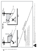
4. Engage the transmission bypass rods on
each side of the tractor; then carefully roll
the tractor off the shipping pallet. The
transmission bypass rods (one for each the
RH and LH transmission) are located on the
rear of the tractor, just inside each rear wheel.
Engage the bypass rods by pulling each one
out and to the right then letting it return to
lock it into place. See Figure 2-1.
a
a
b
Figure 2-1
5. Disengage the bypass rods after rolling the
tractor off the pallet. See Figure 2-1.
Contents of Crate
• Zero-Turn Tractor (1) • Operator’s Manual (1) • Engine Operator’s Manual (1)
• Oil Drain Tube (1) • Deck Wash Hose Coupler (1) • Hardware Pack (1)
6. Remove the deck wash system nozzle
adapter from the manual bag and store for
future use.
Securing the Steering Column (Non-Tilt Tractors)
The steering column is tilted all the way back for
shipping. Place the steering column in one of the
two positions and secure in place with the hex
screws (a) and flat washers (b) packed separately.
See Figure 2-2.
(b)
(a)
(a)
(b)
Figure 2-2
Securing the Steering Column (Tractors w/ Tilt
Steering)
The steering column is shipped all the way back for
shipping. Lift the steering column up until it clicks
into the lowest tilt position. Then the steering
column can be adjusted to the desired height as
instructed in the Controls & Operations section.
Installing the Console (If necessary)
7. Connect the headlight harness/12V wiring
harness to the main harness. Make sure the
D-shape connectors align properly. See
Figure 2-3.
Figure 2-3
8. Slide the console onto the steering column
with the wiring harness tucked in behind
the console. Make sure the lower portion of
the console is inside the lower column cover.
See Figure 2-4 and Figure 2-5.
Figure 2-4