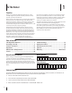
Safe Operation Practices • Set-Up • Operation • Maintenance • Service • Troubleshooting • Warranty Operator’s Manual Hydrostatic Lawn Tractor — SLTX 1050, 1054 & 1054VT WARNING READ AND FOLLOW ALL SAFETY RULES AND INSTRUCTIONS IN THIS MANUAL BEFORE ATTEMPTING TO OPERATE THIS MACHINE. FAILURE TO COMPLY WITH THESE INSTRUCTIONS MAY RESULT IN PERSONAL INJURY. CUB CADET LLC, P.O. BOX 361131 CLEVELAND, OHIO 44136-0019 Printed In USA Form No.
1 To The Owner Thank You Thank you for purchasing a Cub Cadet Lawn Tractor. It was carefully engineered to provide excellent performance when properly operated and maintained. Please read this entire manual prior to operating the equipment. It instructs you how to safely and easily set up, operate and maintain your machine. Please be sure that you, and any other persons who will operate the machine, carefully follow the recommended safety practices at all times.
Important Safe Operation Practices 2 WARNING! This symbol points out important safety instructions which, if not followed, could endanger the personal safety and/or property of yourself and others. Read and follow all instructions in this manual before attempting to operate this machine. Failure to comply with these instructions may result in personal injury. When you see this symbol.
12. A missing or damaged discharge cover can cause blade contact or thrown object injuries. 13. Stop the blade(s) when crossing gravel drives, walks, or roads and while not cutting grass. 14. Watch for traffic when operating near or crossing roadways. This machine is not intended for use on any public roadway. 15. Do not operate the machine while under the influence of alcohol or drugs. 16. Mow only in daylight or good artificial light. 17. Never carry passengers. 18.
Children Service 1. Safe Handling of Gasoline: Tragic accidents can occur if the operator is not alert to the presence of children. Children are often attracted to the machine and the mowing activity. They do not understand the dangers. Never assume that children will remain where you last saw them. a. Keep children out of the mowing area and in watchful care of a responsible adult other than the operator. b. Be alert and turn machine off if a child enters the area. c.
Periodically check to make sure the blades come to complete stop within approximately (5) five seconds after operating the blade disengagement control. If the blades do not stop within the this time frame, your machine should be serviced professionally by an authorized MTD Service Dealer. Do not modify engine 4. Check brake operation frequently as it is subjected to wear during normal operation. Adjust and service as required. Notice Regarding Emissions 5.
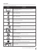
Safety Symbols This page depicts and describes safety symbols that may appear on this product. Read, understand, and follow all instructions on the machine before attempting to assemble and operate. Symbol Description READ THE OPERATOR’S MANUAL(S) Read, understand, and follow all instructions in the manual(s) before attempting to assemble and operate DANGER— ROTATING BLADES Never carry passengers. Never carry children, even with the blades off.
Section 2 — Important Safe Operation Practices d line dotte (repr esent ing a 15° s lope) or a fence post WARNING! Do not operate your lawn mower on such slopes. Do not mow on inclines with a slope in excess of 15 degrees (a rise of approximately 2-1/2 feet every 10 feet). A riding mower could overturn and cause serious injury. Operate riding mowers up and down slopes, never across the face of slopes. Use this page as a guide to determine slopes where you may not operate safely.
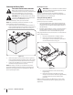
3 Assembly & Set-Up Contents of Crate • One Lawn Tractor • • One Lawn Tractor Operator’s Manual • One Oil Drain Tube One Deck Wash Hose Coupler One Engine Operator’s Manual Tractor Set-Up Shipping Brace Removal Warning! Make sure the lawn tractor’s engine is off, set the parking brake and remove the ignition key before removing the shipping brace.
Connecting the Battery Cables Checking Tire Pressure Warning! Do not overinflate tires. Check sidewall of tires for maximum psi. Equal tire pressure should be maintained at all times. California Proposition 65 Warning: Battery posts, terminals, and related accessories contain lead and lead compounds, chemicals known to the State of California to cause cancer and reproductive harm. Wash hands after handling.
Adjusting the Seat To adjust the position of the seat, pull up and hold the seat adjustment lever. Slide the seat forward or rearward to the desired position; then release the adjustment lever. Make sure seat is locked into position before operating the tractor. See Fig. 3-5. Figure 3-5 Warning! Before operating the tractor, make sure the seat is engaged in the seat-stop. Engage the parking brake. Stand behind the machine and pull back on seat until it clicks into place.
4 Controls and Features Systems Indicator Monitor Fuel Tank Cap Ignition Switch Module Throttle/Choke Control Electric PTO Knob Fuel Level Indicator Brake Pedal Cargo Net Drive Pedal Parking Brake/ Cruise Control Lever Reverse Pedal Deck Lift Lever Seat Adjustment Lever Storage Bin Cup Holder Figure 4-1 Lawn Tractor controls and features are illustrated in Fig. 4-1 and Throttle/Choke Control Lever described on the following pages.
Deck Lift Lever Found on your tractor’s right fender, the deck lift lever is used to change the height of the cutting deck. To use, move the lever to the left, then place in the notch best suited for your application. Ignition Switch Module Warning! Never leave a running machine unattended. Always disengage PTO, set parking brake, stop engine and remove key to prevent unintended starting. To start the engine, insert the key into the ignition switch and turn clockwise to the START position.
Fuel Level Indicator Parking Brake/Cruise Control Lever The Fuel Level Indicator is located on the left side of the tractor’s dash and indicates the amount of fuel in the gas tank. PTO / Blade Engage Knob Activating the PTO engages power to the cutting deck or other (separately available) attachments. Pull outward on the PTO/Blade Engage knob to activate it. Push the PTO/ Blade Engage knob inward to disengage the power to the cutting deck or other (separately available) attachments.
5 Operation Starting the Engine TO AVOID SERIOUS INJURY OR DEATH • • • • • • • • • GO UP AND DOWN SLOPES, NOT ACROSS. AVOID SUDDEN TURNS. DO NOT OPERATE THE UNIT WHERE IT COULD SLIP OR TIP. IF MACHINE STOPS GOING UPHILL, STOP BLADE(S) AND BACK DOWNHILL SLOWLY. KEEP SAFETY DEVICES (GUARDS, SHIELDS, AND SWITCHES, ETC.) IN PLACE AND WORKING. REMOVE OBJECTS THAT COULD BE THROWN BY THE BLADE(S). KNOW LOCATION AND FUNCTION OF ALL CONTROLS.
Driving The Tractor WARNING! Avoid sudden starts, excessive speed and sudden stops. Note: While on pavement, operating the power steering with the engine running and the tractor at a stand-still, may cause the front wheels to stutter. This is considered normal and will operate smoothly under typical mowing conditions. Reverse Caution Mode 1. Lightly press the brake pedal to release the parking brake. Move the throttle lever into the FAST (rabbit) position.
Driving On Slopes Cruise Control Warning! Never engage the cruise control lever while traveling in reverse. Refer to the SLOPE GAUGE on page 8 to help determine slopes where you may operate the tractor safely. WARNING! Do not mow on inclines with a slope in excess of 15 degrees (a rise of approximately 2-1⁄2 feet every 10 feet). The tractor could overturn and cause serious injury. To set the cruise control: 1.
Engaging the PTO Mowing Warning! To help avoid blade contact or a thrown object injury, keep bystanders, helpers, children and pets at least 75 feet from the machine while it is in operation. Stop the machine if anyone enters the area. Engaging the PTO transfers power to the cutting deck or other (separately available) attachments. To engage the PTO: 1. Move the throttle control lever to the FAST (rabbit) position.
6 Maintenance & Adjustments Maintenance Schedule Before Each use Every 10 Hours Check Air Filter for Dirty, Loose or Damaged Parts Every 50 Hours Every 100 Hours P Clean Hood/Dash Louvers Check Engine Oil Level Every 25 Hours Prior to Storing P P P P Clean and Re-oil Air Filter’s Foam Precleaner P Replace Air Filter Element P Change Engine Oil and Replace Oil Filter Clean Battery Terminals P P P P Lube Front Axles and Rims Clean Engine Cooling Fins Lube Front Deck Wheels Lube Pedal Pivot P
3. Pop open the protective cap on the end of the oil drain valve to expose the drain port. See Fig 6-1. Hydrostatic Transmission The hydrostatic transmission is sealed at the factory and is maintenance-free. The fluid level cannot be checked and the fluid cannot be changed. Battery California Proposition 65 Warning! Battery posts, terminals, and related accessories contain lead and lead compounds, chemicals known to the State of California to cause cancer and reproductive harm. Wash hands after handling.
4. Attach the hose coupler to the water port on your decks surface. See Fig. 6-2. Lubrication Warning! Before lubricating, repairing, or inspecting, always disengage PTO, set parking brake, stop engine and remove key to prevent unintended starting. Front Wheels Each of the front wheel axles and rims is equipped with a grease fitting. See Fig. 6-3. Lubricate with a No. 2 multi-purpose grease applied with a grease gun after every 25 hours of tractor operation. Figure 6-2 5. Turn the water on. 6.
Adjustments WARNING! Shut the engine off, remove the ignition key and engage the parking brake before making adjustments. Protect your hands by using heavy gloves when handling the blades. Determine the approximate distance necessary for proper adjustment and proceed, if necessary. 1. Locate the flange lock nut on the end of the deck hanger rod. See Fig. 6-4. NOTE: Check the tractor’s tire pressure before performing any deck leveling adjustments.
Leveling the Deck (Side to Side) Steering Adjustment If the cutting deck appears to be mowing unevenly, a side to side adjustment can be performed. Adjust if necessary as follows: If the tractor turns tighter in one direction than the other, or if the ball joints are being replaced due to damage or wear, the steering drag links may need to be adjusted. 1.
7 Service Cutting Deck Removal NOTE: If there is too much tension on the belt for it to be easily removed from the electric PTO clutch, carefully insert a 3⁄8” drive ratchet wrench (set to tighten) into the square hole found in the left-hand deck idler bracket and pivot it toward the tractor’s right side to relieve tension on the belt. See Fig. 7-2. To remove the cutting deck, proceed as follows: 1. Place the PTO/Blade Engage knob in the disengaged (OFF) position and engage the parking brake. 2.
6. Pull the deck support pin outward to release the deck from the deck lift arm. See Fig. 7-3. Deck Lift Arm Deck Support Pin Cutting Blades WARNING! Shut the engine off and remove ignition key before removing the cutting blade(s) for sharpening or replacement. Protect your hands by using heavy gloves when grasping the blade. Figure 7-3 7. Repeat the above steps on the tractor’s right side. 8. Move the deck lift lever into the top notch to raise the deck lift arms up and out of the way. 9.
4. To properly sharpen the cutting blades, remove equal amounts of metal from both ends of the blades along the cutting edges, parallel to the trailing edge, at a 25° to 30° angle. Always grind each cutting blade edge equally to maintain proper blade balance. See Fig. 7-7. Battery California Proposition 65 Warning: Battery posts, terminals, and related accessories contain lead and lead compounds, chemicals known to the State of California to cause cancer and reproductive harm. Wash hands after handling.
Fuse Changing the Deck Belt WARNING! Before servicing, repairing, or inspecting, always disengage PTO, set parking brake, stop engine and remove key to prevent unintended starting. WARNING! Shut the engine off and remove ignition key before removing the cutting blade(s) for sharpening or replacement. Protect your hands by using heavy gloves when grasping blades and pulleys.
5. To place the new belt begin by routing the belt around the two outer spindle pulleys, then around the front spindle pulley as shown in Fig. 7-9. Deck Idler Pulleys 9. Pull the right side of the belt and place the narrow V side of the belt into the PTO pulley. See Fig. 7-10. Front Spindle Pulley PTO Belt Rotate Pulley Outer Spindle Pulleys Figure 7-9 6. Route the belt around the two deck idler pulleys as shown in Fig. 7-9. 7. Reinstall the belt keeper rod loosened earlier.
8 Troubleshooting Problem Engine fails to start Cause Remedy 1. PTO/Blade Engage knob engaged. 1. Place knob in disengaged (OFF) position. 2. Parking brake not engaged. 2. Engage parking brake. 3. Spark plug wire(s) disconnected. 3. Connect wire(s) to spark plug(s). 4. Throttle control lever not in correct starting position. 4. Place throttle lever to FAST position. 5. Choke not activated 5. Move the Throttle/Choke Control into choke position. 6. Fuel tank empty, or stale fuel. 6.
9 Replacement Parts Component Part Number and Description 759-3336 Spark Plug KH-32-883-03-S1 Air Filter and Pre-cleaner KH-12-050-01-S Oil Filter KH-25-050-22-S1 Fuel Filter 954-04077 954-0642 Deck Drive Belt (50” Deck) Deck Drive Belt (54” Deck) 942-04053C 942-0677B 2-in-1 Deck Blade (50” Deck) 2-in-1 Deck Blade (54” Deck) 918-04125B Deck Spindle (50” & 54” Decks) Phone (800) 965-4CUB to order replacement parts or a complete Parts Manual (have your full model number and serial number ready).
Component Part Number and Description 734-04155 Deck Wheel 925-1707D Battery 951-12179 Fuel Tank Cap 946-04556 Throttle/Choke Control Cable 925-2054A Ignition Key 631-04070A Discharge Chute Assembly Phone (800) 965-4CUB to order replacement parts or a complete Parts Manual (have your full model number and serial number ready). Parts Manual downloads are also available free of charge at www.cubcadet.
10 Attachments & Accessories The following attachments and accessories are compatible for Cub Cadet SLTX1050, 1054 and 1054VT. Call (800) 965-4CUB or see your Cub Cadet dealer or the retailer from which you purchased your tractor for information regarding price and availability. Caution: Cub Cadet Series 1000 lawn tractors are NOT designed for use with any type of ground-engaging attachments (e.g. tiller or moldboard plow). Use of this type of equipment WILL void the tractor’s warranty.
Notes 11 33
FEDERAL and/or CALIFORNIA EMISSION CONTROL WARRANTY STATEMENT YOUR WARRANTY RIGHTS AND OBLIGATIONS MTD Consumer Group Inc, the United States Environmental Protection Agency (EPA), and, for those products certified for sale in the state of California, the California Air Resources Board (CARB) are pleased to explain the emission (evaporative and/or exhaust) control system (ECS) warranty on your outdoor 2006 and later small off-road spark-ignited engine and equipment (outdoor equipment engine) In California, n
WARRANTED PARTS: The repair or replacement of any warranted part otherwise eligible for warranty coverage may be excluded from such warranty coverage if MTD Consumer Group Inc demonstrates that the outdoor equipment engine has been abused, neglected, or improperly maintained, and that such abuse, neglect, or improper maintenance was the direct cause of the need for repair or replacement of the part.
CUB CADET LLC MANUFACTURER’S LIMITED WARRANTY FOR SERIES 1000 & SERIES 1500 TRACTORS IMPORTANT: To obtain warranty coverage owner must present an original proof of purchase and applicable maintenance records to the servicing dealer. Please see the operator’s manual for information on required maintenance and service intervals. In the U.S.A.: Check your Yellow Pages, or contact Cub Cadet LLC at P.O. Box 361131, Cleveland, Ohio 44136-0019, call 1-877-282- 8684 or log on to our website at www.cubcadet.com.
Medidas importantes de seguridad • Configuración • Funcionamiento • Mantenimiento • Servicio • Solución de problemas • Garantía Manual del Operador Tractor Corta Césped Hidrostático — SLTX 1050, 1054 & 1054VT ADVERTENCIA LEA Y SIGA TODAS LAS INSTRUCCIONES DE ESTE MANUAL ANTES DE PONER EN FUNCIONAMIENTO ESTA MÁQUINA. SI NO RESPETA ESTAS INSTRUCCIONES PUEDE PROVOCAR LESIONES PERSONALES. CUB CADET LLC, P.O.
1 Al propietario Gracias Gracias por comprar una Cub Cadet tractor corta césped. El mismo ha sido diseñado cuidadosamente para brindar excelente rendimiento si se lo opera y mantiene correctamente. Por favor lea todo este manual antes de operar el equipo. Le indica cómo configurar, operar y mantener la máquina con seguridad y fácilmente.
2 Medidas importantes de seguridad ADVERTENCIA: La presencia de este símbolo indica que se trata de instrucciones importantes de seguridad que se deben respetar para evitar poner en peligro su seguridad personal y/o material y la de otras personas. Lea y siga todas las instrucciones de este manual antes de poner en funcionamiento esta máquina. Si no respeta estas instrucciones puede provocar lesiones personales. Cuando vea este símbolo.
10. Esté atento a la cortadora y a la dirección de la descarga de los aditamentos y no apunte a nadie. Nunca opere la cortadora de césped sin que estén en su lugar apropiado la cubierta de descarga o el colector de recortes de césped. 11. No ponga las manos o los pies cerca de las piezas rotatorias o debajo de la plataforma de corte. El contacto con las cuchillas puede producir la amputación de manos y pies. 12.
6. 7. No cambie a transmisión neutral para descender. El exceso de velocidad puede hacer que el operador pierda el control de la máquina, ocasionando lesiones graves e incluso la muerte. No remolque cargas pesadas detrás de los aditamentos (carrito de basura cargado, podadora de rodillos, etc) en pendientes mayores de 5 grados.
2. 3. 4. 5. 6. 7. 8. 9. 10. 11. 12. 13. 14. Antes de limpiar, reparar o inspeccionar la máquina, compruebe que la(s) cuchilla(s) y todas las partes en movimiento se hayan detenido. Desconecte el cable de la bujía y póngalo haciendo masa contra el motor para evitar que se encienda accidentalmente. Revise periódicamente para asegurarse que las cuchillas se detengan por completo en aproximadamente cinco (5) segundos después de accionar el control de desenganche de la(s) cuchilla(s).
Safety Symbols This page depicts and describes safety symbols that may appear on this product. Read, understand, and follow all instructions on the machine before attempting to assemble and operate. Symbol Description LEA EL MANUAL(S) DEL OPERADOR leído, entienda, y siga todas las instrucciones en el manual(s) antes de procurar montar y funcionar PELIGRO— DÉ EL CORTE DE PIE Nunca transporte pasajeros. Nunca transporte niños, aún con la cuchilla apagada. PELIGRO— DÉ EL CORTE DE PIE Retroceda lentamente.
Mire y mantenga este nivel con un árbol vertical o la esquina de un edificio... p °) endi e n t e d e 15 o el poste de una empalizada e pun t o s ( r epre s e n t a una ad Doble p o r l a líne 15° Use esta página como guía para determinar en qué pendientes no puede operar el tractor de manera segura. ADVERTENCIA: No opere la cortadora de césped en dichas pendientes. No corte en inclinaciones mayores de 15 grados (elevación aproximada de 2 1/2 pies por cada 10 pies).
3 Montaje y Configuración Contenido del cajón • Un tractor corta césped • Un tubo de drenaje de aceite • Un Manual del operador del tractor corta césped • Un Manual del operador del motor Configuración del tractor 1.
Instalación del cable de la baterías Control de la presión de los neumáticos PROPUESTA 65 DE CALIFORNIA ADVERTENCIA! Los postes de la batería, terminales y accesorios relacionados contienen plomo y compuestos químicos, conocidos por el Estado de California que causan cáncer y daños en la reproducción. Lávese las manos después de la manipulación.
d. Vuelva a insertar el tornillo con reborde (con cada rueda de calibración) dentro del orificio de posicionamiento que deja aproximadamente ½ pulgada entre la parte inferior de la rueda y el pavimento. Consulte la sección Nivelación de la plataforma en la sección Mantenimiento de este manual para obtener instrucciones detalladas sobre diferentes ajustes de la plataforma. Ajuste del asiento Para ajustar la posición del asiento, tire hacia arriba y mantenga la sede de ajuste.
4 Controles y Características Monitor del indicador de sistemas Módulo del interruptor de encendido Tapón del tanque de combustible Interruptor de la potencia de arranque (PTO) Control del regulador/cebador Indicador de nivel de combustible Pedal de la transmisión Pedal de freno Cargo Neto Palanca de ajuste del asiento Freno de mano / palanca de control de crucero Bin almacenamiento Pedal de la marcha atrás Palanca de elevación de la plataforma Ahueque a Poseedor Figure 4-1 Los controles y carac
Palanca de elevación de la plataforma Ubicada en el guardabarros derecho del tractor, la palanca de elevación de la plataforma se utiliza para cambiar la altura de la plataforma de corte. Para utilizarla, mueva la palanca hacia la izquierda, luego colóquela en la muesca que mejor se adapte a la aplicación deseada. Módulo del interruptor de encendido ¡Advertencia! Nunca deje la máquina en funcionamiento sin vigilancia.
Cargo Neto La carga neta se encuentra en la mitad inferior de la raya y puede utilizarse para el almacenamiento. Indicador de nivel de combustible El indicador de nivel de combustible está ubicado a la derecha del panel de instrumentos del tractor e indica la cantidad de combustible en el tanque. Localizada en el centro del panel de instrumentos del tractor debajo del volante, el freno de mano/palanca de control de crucero se utiliza para conectar el freno de mano y el control de crucero.
5 Funcionamiento ¡Advertencia! No opere el tractor si el sistema de bloqueo funciona mal. Este sistema fue diseñado para brindarle seguridad y protección. ADVERTENCIA PARA EVITAR LESIONES PERSONALES GRAVES O LA MUERTE • EN LAS PENDIENTES PODE HACIA ARRIBA Y HACIA ABAJO, NO DE FORMA TRANSVERSAL. • EVITE MANIOBRAS DE GIRO BRUSCAS.
Conducción del tractor Modo de precaución en marcha atrás ¡ADVERTENCIA! Evite arrancar súbitamente, desarrollar excesiva velocidad y detenerse de repente. 1. 2. Presione levemente el pedal del freno para liberar el freno de mano. Mueva la palanca del regulador a la posición FAST (VELOCIDAD RÁPIDA, representada por una liebre). La posición MODO DE PRECAUCIÓN EN MARCHA ATRÁS del módulo del interruptor de llave permite operar el tractor en marcha atrás con las cuchillas (toma de fuerza - PTO) enganchadas.
El MODO DE PRECAUCIÓN EN MARCHA ATRÁS permanece activado hasta que: a. Se coloque la llave en la posición CORTE NORMAL o en la posición STOP (detención) o b. El operador abandona el asiento. Operación en pendientes Consulte la sección INDICADOR DE PENDIENTE en la página 8 para determinar en qué pendientes puede operar el tractor de manera segura. ¡ADVERTENCIA! No corte el césped en inclinaciones mayores a 15 grados (elevación aproximada de 2-1⁄2 pies cada 10 pies).
IMPORTANTE: Es importante utilizar siempre el tractor con el acelerador en la posición FAST (liebre) para garantizar la correcta carga de la batería. • Para obtener los mejores resultados, se recomienda realizar los dos primeros cortes de césped arrojando la descarga hacia el centro. Después de las dos primeras vueltas, cambie la dirección para arrojar la descarga hacia afuera, para equilibrar el corte. Esto otorgará un mejor aspecto al césped.
6 Mantenimiento y Ajustes Calendario de mantenimiento Antes de cada uso Controle el filtro de aire para ver si hay piezas sucias, sueltas o dañadas Cada 25 horas Cada 50 horas Cada 100 horas P Limpie el capó/los respiraderos Inspeccione el nivel de aceite del motor Cada 10 horas Antes de almacenar P P P Limpie y vuelva a lubricar el depurador de espuma del filtro de aire P P Reemplace el elemento del filtro de aire Cambie el aceite del motor y reemplace el filtro de aceite Limpie los bornes de
2. Abra el capó del tractor y ubique el puerto de drenaje de aceite del lado izquierdo del motor. Vea la Fig. 6-1. 8. Cuando termine de drenar el aceite, empuje el extremo de la válvula de drenaje de aceite hacia adentro, hasta que las lengüetas calcen en su lugar. Vuelva a tapar el extremo de la válvula de drenaje para evitar que entren residuos en el orificio de drenaje. 9. Cambie el filtro de aceite según las instrucciones del Manual Propietario Kohler. 10.
Smart Jet™ 10. La plataforma de su tractor está equipada con un puerto de agua sobre su superficie como parte del sistema de lavado de la plataforma. Gire la llave de encendido a la posición STOP (detención) para apagar el motor del tractor. 11. Desconecte el agua y retire el acoplador de la manguera desde el puerto de agua que se encuentra en la superficie de la plataforma.
Ajustes ¡ADVERTENCIA! Apague el motor, retire la llave de encendido y coloque el freno de mano antes de realizar ajustes. Proteja sus manos utilizando guantes pesados cuando maneje las cuchillas. Determine la distancia aproximada necesaria para un ajuste adecuado y, de ser necesario, proceda. 4. Localice la tuerca de seguridad con brida en el extremo de la barra de suspensión de la plataforma. Véase la figura. 6-4.
¡Advertencia! Antes de operar el tractor, asegúrese de que el asiento esté enganchado en el tope del asiento. Coloque el freno de mano. Párese detrás de la máquina y tire del asiento hacia atrás hasta que encaje en su lugar haciendo clic. Nivelación de la plataforma (lado a lado) Si la plataforma de corte estuviera realizando el corte de césped de forma despareja, puede realizarse un ajuste lado a lado. De ser necesario, realice un ajuste de la siguiente manera: 1. 2. 3.
7 Servicio Extracción de la plataforma de corte NOTA: Si hay demasiada tensión en la correa para que sea quitada fácilmente del embrague eléctrico del PTO, inserte cuidadosamente” llave de trinquete de impulsión un 3⁄8 (fije para apretar) en la perforación rectangular encontrada en el soporte más ocioso de la cubierta izquierda y gírelo hacia el derecho del tractor para relevar la tensión en la correa. Vea Fig. 7-2. Para extraer la plataforma de corte, proceda de la siguiente manera: 1.
5. Tire hacia afuera el pasador de soporte de la plataforma para separar la misma del brazo de elevación de la plataforma. Vea la Fig. 7-3. Cuchillas de corte ¡ADVERTENCIA! Apague el motor y extraiga la llave de contacto antes de retirar las cuchillas de corte para afilado o reemplazo. Proteja sus manos utilizando guantes reforzados cuando maneje las cuchillas.
4. Para afilar las cuchillas de corte de forma adecuada, extraiga cantidades iguales de metal de ambos extremos de las cuchillas a lo largo de los bordes cortantes, de forma paralela al borde de caída, a un ángulo de 25° a 30°. Afile siempre cada borde de las cuchillas de corte de forma pareja para mantener un equilibrio adecuado entre las mismas. Vea la Fig. 7-6.
2. Si el cargador de su batería es automático, cargue la batería hasta que el cargador indique que se ha completado la carga. Si el cargador no es automático, cargue por ocho horas como mínimo. Cambio de la correa de la plataforma ¡ADVERTENCIA! Apague el motor y extraiga la llave de contacto antes de retirar las cuchillas de corte para afilado o reemplazo. Proteja sus manos utilizando guantes reforzados cuando maneje las cuchillas y las poleas.
5. Para colocar la nueva correa comience encaminando la correa alrededor de las dos poleas de huso externas, entonces alrededor de la polea de huso delantera según las indicaciones de Fig. 7-8. Cubierta de la polea poleas 10. Tire del derecho de la correa y ponga el lado estrecho de V de la correa en la polea del PTO. Vea Fig. 7-9. Frente polea del husillo Correa de la PTO Girar la polea Exterior del husillo poleas Figura 7-9 Figura 7-8 64 6.
8 Solución de Problemas Problem El motor no arranca El motor funciona de manera errática El motor recalienta Cause Remedy 1. Palanca de potencia de arranque (PTO) / enganche de cuchilla conectada. 1. Coloque la perilla en la posición de desconexión (OFF). 2. No está colocado el freno de mano. 2. Coloque el freno de mano. 3. Se ha desconectado el cable de la bujía. 3. Conecte el cable a la bujía. 4. La palanca de control del regulador/cebador no está en la posición de arranque correcta. 4.
Problem Remedy El motor vacila a altas revoluciones 1. La separación de la bujía es muy pequeña. 1. Retire la bujía y reajuste la separación. El motor funciona con dificultad en ralentí 1. Bujía sucia, averiada o exceso de separación. 1. Reemplace la bujía. Ajuste la separación de la bujía. 2. El filtro de aire está sucio. 2. Reemplace el elemento del filtro de aire y/o limpie el depurador. 1. Cuchilla de corte floja o descentrada. 1. Apriete la cuchilla y el husillo. 2.
9 Piezas de reemplazo Componente Número de pieza y Descripción 759-3336 Bujía (Champion RC12YC) KH-32-883-03-S1 Limpiador de Aire Elemento con Pre-Filtro KH-12-050-01-S Filtro de Aceite KH-25-050-22-S1 Filtro de Combustible 954-04077 954-0642 942-04053C 942-0677B 918-04125B Cubierta de la correa de transmisión (50 “de la cubierta) Cubierta de la correa de transmisión (54 “de la cubierta) 2-in-1 Cuchilla de Plataforma 50” Cubierta 2-in-1 Cuchilla de Plataforma 54” Cubierta Husilla de Plataforma (
Componente Número de pieza y Descripción 734-04155 Rueda de Plataforma (Frente) 925-1707D Batería 951-12179 Tapa del Tanque de Combustible 946-04556 Cable de Control de Regulador/ Cebador 925-2054A Llave de Encendido 631-04070A Asamblea de Canal de Descarga Llame por teléfono al (800) 965-4CUB para solicitar piezas de reemplazo o un Manual de Piezas de Repuesto completo (tenga el número de modelo y número de serie de su máquina a mano). En www.cubcadet.
10 Aditamentos y Accesorios Los siguientes aditamentos y accesorios son compatibles con el SLTX1050, 1054 & 1054VT. Llame (800) 965-4CUB para la información con respecto a la compatibilidad, el precio y la disponibilidad (tener su número de modelo completo y número de serie). Precaución: Cub Cadet tractores del césped de la serie 1000 no están diseñados para su uso con cualquier tipo de acoplamiento de tierra adjuntos(por ejemplo, caña o arado de vertedera).
DECLARACIÓN FEDERAL y/o DE CALIFORNIA SOBRE GARANTÍAS EN EL CONTROL DE EMISIONES SUS DERECHOS Y OBLIGACIONES EN CUANTO A LA GARANTÍA MTD Consumer Group Inc, la Agencia de Protección Medioambiental de los Estados Unidos (EPA), y para aquellos productos certificados para su venta en el estado de California, el Departamento de los Recursos del Aire de California (CARB) se complacen en explicar la garantía que cubre al sistema de control (ECS) de emisiones (evaporativas y/o de escape) de su equipo y motor (moto
8. Durante la totalidad del período de garantía del motor y equipo para todo terreno arriba mencionado, MTD Consumer Group Inc mantendrá un suministro de piezas bajo garantía suficiente para satisfacer la demanda esperada de tales piezas. 9. Cualquier pieza de reemplazo se podrá usar para el cumplimiento del mantenimiento o las reparaciones bajo garantía y se suministrarán sin cargo para el propietario. Dicho uso no reducirá las obligaciones de garantía de MTD Consumer Group Inc. 10.
GARANTÍA LIMITADA DEL FABRICANTE CUB CADET LLC PARA TRACTORES DE SERIE 1000 Y SERIE 1500 IMPORTANTE: Para obtener cobertura de garantía, el propietario debe presentar una evidencia original de la compra y los registros de mantenimiento correspondientes al centro de servicio técnico autorizado del distribuidor. Consulte el manual del operador para obtener información sobre los intervalos de mantenimiento y servicio requeridos.