Safe Operation Practices • Set-Up • Operation • Maintenance • Service • Troubleshooting • Warranty Operator’s Manual 22-inch String Trimmer — Model Series 260 WARNING READ AND FOLLOW ALL SAFETY RULES AND INSTRUCTIONS IN THIS MANUAL BEFORE ATTEMPTING TO OPERATE THIS MACHINE. FAILURE TO COMPLY WITH THESE INSTRUCTIONS MAY RESULT IN PERSONAL INJURY. CUB CADET LLC, P.O. BOX 361131 CLEVELAND, OHIO 44136-0019 Form No.
1 To The Owner Thank You Thank you for purchasing a Lawn Mower manufactured by Cub Cadet. It was carefully engineered to provide excellent performance when properly operated and maintained. If applicable, the power testing information used to establish the power rating of the engine equipped on this machine can be found at www.opei.org or the engine manufacturer’s web site. Please read this entire manual prior to operating the equipment.
Important Safe Operation Practices 2 WARNING: This symbol points out important safety instructions which, if not followed, could endanger the personal safety and/or property of yourself and others. Read and follow all instructions in this manual before attempting to operate this machine. Failure to comply with these instructions may result in personal injury. When you see this symbol.
11. Do not put hands or feet near or under rotating parts. Keep clear of discharge area at all times as the rotating spindle and trimmer lines can cause injury. 12. Never operate the string trimmer without proper shields, guards, control lever or other safety protective devices in place and working. 13. Never operate the string trimmer with damaged safety devices. Failure to do so, can result in personal injury. 14.
4. Use extreme care when approaching blind corners, doorways, shrubs, trees, or other objects that may obscure your vision of a child who may run into the string trimmer. 5. Keep children away from hot or running engines. They can suffer burns from a hot muffler. 6. Before cleaning, repairing, or inspecting, make certain the spindle and all moving parts have stopped. Disconnect the spark plug wire and ground against the engine to prevent unintended starting. 3.
Notice Regarding Emissions Engines which are certified to comply with California and federal EPA emission regulations for SORE (Small Off Road Equipment) are certified to operate on regular unleaded gasoline, and may include the following emission control systems: Engine Modification (EM), Oxidizing Catalyst (OC), Secondary Air Injection (SAI) and Three Way Catalyst (TWC) if so equipped.
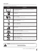
Safety Symbols This page depicts and describes safety symbols that may appear on this product. Read, understand, and follow all instructions on the machine before attempting to assemble and operate. Symbol Description READ THE OPERATOR’S MANUAL(S) Read, understand, and follow all instructions in the manual(s) before attempting to assemble and operate EYE PROTECTION Always wear safety glasses or safety goggles when operating this machine.
Section 2 — Important Safe Operation Practices Figure 1 line Figure 2 (TOO STEEP) WARNING! Slopes are a major factor related to slip and fall accidents which can result in severe injury or death. Do not operate machine on slopes in excess of 15 degrees. All slopes require extra caution. Always mow across the face of slopes, never up and down slopes. To check the slope, proceed as follows: 1. Remove this page and fold along the dashed line. 2. Locate a vertical object on or behind the slope (e.g.
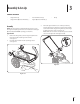
3 Assembly & Set-Up Contents of Carton • String Trimmer (1) • • String Trimmer Operator’s Manual (1) • Pack of Trimmer Line (1) • Oil (1) Engine Operator’s Manual (1) Assembly 3. NOTE: This string trimmer is shipped without gasoline or oil in the engine. Fill up the gasoline and oil as instructed in the Engine Operator’s Manual BEFORE operating your machine. Upper Handle 1. Remove the wing knob (a) and carriage bolt (b) from the left lower handle and the right lower handle. See Figure 3-1. 2.
Starter Rope Set-Up 1. Disconnect the spark plug boot from the spark plug (refer to the Engine Operator’s Manual). Gas and Oil Fill-Up 2. Pivot the control handle against the upper handle and pull the rope out of the engine. 3. Loop the rope through the eye bolt. See Figure 3-3. 4. Tighten the eye bolt to the handle using the lock nut. DO NOT overtighten. Figure 3-3 10 Section 3 — Assembly & Set-Up Refer to the Engine Operator’s Manual for additional engine information. 1.
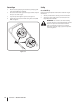
4 Controls and Features Control Lever Recoil Starter Flywheel Screen Trimmer Line Trimmer Deflector Spindle Figure 4-1 Recoil Starter Spindle The recoil starter is attached to the right side of the upper handle. Stand behind the unit and pull the recoil starter rope to start the unit. The spindle rotates the trimmer line. Trimmer Deflector The trimmer line is attached to the spindle assembly and it is used to trim grass, vegetation, undergrowth and weeds.
5 Operation Adjusting the Spindle Height • The spindle height can be adjusted for various applications. To do so, proceed as follows: Operate the string trimmer at a slower walking speed when trimming tall, thick weeds or grass. • Clean the underside of the trimmer after each use to remove any debris build up. 1. Loosen the wing nut found on each side of the spindle shaft. WARNING: Shut the engine off and wait until the trimmer head comes to a complete stop before cleaning the discharge area.
6 Maintenance & Adjustments Maintenance Deck Care General Recommendations Clean underside of the machine after each use to prevent buildup of grass clippings or other debris. • Always observe safety rules when performing any maintenance. 1. Allow engine to run until it is out of fuel. Do not attempt to pour fuel from the engine. Disconnect spark plug wire. • The warranty on this string trimmer does not cover items that have been subjected to operator abuse or negligence.
7 Troubleshooting Problem Engine fails to start Remedy 1. Control lever disengaged. 1. Engage control lever. 2. Spark plug boot disconnected. 2. Connect wire to spark boot. 3. Fuel tank empty or stale fuel. 3. Fill tank with clean, fresh gasoline. 4. Engine not primed (if equipped with primer). 4. Prime engine as instructed in the Operation section. 5. Faulty spark plug. 5. Clean, adjust gap, or replace. 6. Blocked fuel line. 6. Clean fuel line. 7. Engine flooded. 7.
8 Replacement Parts Component Part Number and Description 951-14437 Spark Plug 951-10298 Air Cleaner Kit 951-14407 Fuel Cap Assembly 951-10358A Fuel Filter 946-05141 Control Cable, 40” 734-04030 Wheel 731-2315 Deflector Flap 731-2329 Trail Shield 490-040-M035 .155” Trimmer Line (Ten-pack) Contact your Cub Cadet dealer to order replacement parts or a complete Parts Manual (have your full model number and serial number ready).
CUB CADET LLC MANUFACTURER’S LIMITED WARRANTY FOR EDGERS, STRING TRIMMERS & TILLERS The limited warranty set forth below is given by Cub Cadet LLC with respect to new merchandise purchased and used in the United States, its possessions and territories, and by MTD Products Limited with respect to new merchandise purchased and used in Canada and/or its territories and possessions. c.
Medidas de seguridad • Configuración • Funcionamiento • Mantenimiento • Servicio • Solución de problemas • Garantía Manual del Operador Orilladora de 22”- Modelo Serie 260 ADVERTENCIA LEA Y OBSERVE TODAS LAS NORMAS E INSTRUCCIONES DE SEGURIDAD INCLUIDAS EN ESTE MANUAL ANTES DE PONER EN FUNCIONAMIENTO LA MÁQUINA. SI NO SIGUE ESTAS INSTRUCCIONES PUEDE PROVOCAR LESIONES PERSONALES. CUB CADET LLC, P.O. BOX 361131 CLEVELAND, OHIO 44136-0019 Formulario No.
1 Al propietario Gracias Gracias por comprar una orilladora Cub Cadet. La misma ha sido cuidadosamente diseñada para brindar excelente rendimiento si se la opera y mantiene correctamente. Por favor lea todo este manual antes de hacer funcionar el equipo. El manual le indica cómo configurar, operar y mantener la máquina con seguridad y fácilmente.
2 Importantes medidas de seguridad ADVERTENCIA: La presencia de este símbolo indica que se trata de instrucciones de seguridad importantes que se deben respetar para evitar poner en peligro su seguridad personal y/o material y la de otras personas. Lea y cumpla todas las instrucciones de este manual antes de intentar operar esta máquina. Si no respeta estas instrucciones puede provocar lesiones personales. Cuando vea este símbolo.
11. 12. Nunca haga funcionar la orilladora sin tener colocados y funcionando los escudos, los protectores, la palanca de control y otros dispositivos de seguridad. 13. Nunca haga funcionar la orilladora si los dispositivos de seguridad están dañados. De lo contrario, pueden producirse lesiones personales. 14. Muchas lesiones ocurren como resultado de pasar la orilladora sobre los pies durante una caída luego de resbalar o tropezar.
5. Mantenga a los niños alejados de los motores en marcha o calientes. Pueden sufrir quemaduras con un silenciador caliente. 6. No permita nunca que los niños menores de 14 años utilicen esta máquina. Los niños de 14 años en adelante deben leer y entender las instrucciones y las normas de seguridad contenidas en este manual y en la máquina y deben ser entrenados y supervisados por un adulto. 2.
Aviso referido a emisiones Los motores que están certificados y cumplen con las normas sobre emisiones federales EPA y de California para SORE (Equipos pequeños todo terreno) están certificados para funcionar con gasolina sin plomo común y pueden incluir los siguientes sistemas de control de emisiones: Modificación de motor (EM), catalizador oxidante (OC), inyección de aire secundaria (SAI) y catalizador de tres vías (TWC) si están instalados.
Símbolos de seguridad En esta página se presentan y describen los símbolos de seguridad que en este producto puede tener. Lea, entienda y siga todas las instrucciones incluidas en la máquina antes de intentar armarla y hacerla funcionar. Símbolo Descripción LEA LOS MANUALES DEL OPERADOR Lea, entienda y siga todas las instrucciones incluidas en los manuales antes de intentar armar la máquina y hacerla funcionar.
8 Sección 2 — Importantes medidas de seguridad Figura 1 iscon tinua nea d 15° lí 15° Pendiente ¡ADVERTENCIA! Las pendientes son un factor importante relacionado con resbalones y caídas de accidentes que pueden producir lesiones graves o la muerte. Corte siempre en sentido transversal a las caras de la pendiente, nunca hacia arriba y abajo. Para evaluar la pendiente, haga lo siguiente: 1. Corté la página del medidor de pendiente y doble a lo largo de la línea discontinua. 2.
3 Montaje y Configuración Contenido de la caja • Una orilladora • Una botella de aceite • Un Manual del operador de la orilladora • Un Manual del operador del motor Montaje 3. NOTA: Esta orilladora se despacha sin gasolina ni aceite en el motor. Llene con gasolina y aceite como se indica en el manual del motor que se acompaña ANTES de hacer funcionar la máquina. Manillar superior 1.
Cuerda de arranque Configuración 1. Desconecte el capuchón de la bujía de la bujía de encendido (consulte en el manual del motor). Llenado de gasolina y aceite 2. Gire la manija de control contra el manillar superior y extraiga del motor la cuerda de arranque tirando de ella. 3. Enhebre la cuerda a través del perno de ojo. Consulte la Figura 3-3. 4. Ajuste el perno de ojo contra la manija con la tuerca de seguridad. NO ajuste demasiado.
4 Controles y Características Palanca de control Arrancador de retroceso Pantalla del volante Hilo de recorte Deflector para orilladora Husillo Figura 4-1 Arrancador de retroceso Husillo El arrancador de retroceso está unido al lado derecho del manillar superior. Para arrancar la unidad colóquese detrás del mismo y tire del cordel del arrancador de retroceso. El husillo hace girar el hilo de recorte.
5 Funcionamiento Ajuste de la altura del husillo • La altura del husillo puede ajustarse para diferentes aplicaciones. Para ello, proceda de la siguiente manera: Haga funcionar la orilladora a una velocidad de paso lento al recortar malezas o pastos gruesos y altos. • Después de cada uso, limpie la parte inferior de la orilladora para eliminar la acumulación de desechos. 1. Afloje las tuercas de mariposa a cada lado del eje del husillo.
6 Mantenimiento y Ajustes Mantenimiento Siga los pasos que aparecen a continuación. Recomendaciones generales • • • • • Respete siempre las reglas de seguridad al realizar tareas de mantenimiento. La garantía de esta orilladora no cubre elementos que han sido sujetos a uso indebido o negligencia del operador. Para recibir el valor total de la garantía, el operador debe mantener la orilladora como se indica en este manual. El cambio de la velocidad controlada del motor invalidará la garantía del motor.
7 Solución de Problemas Problema El motor no arranca Causa 1. La palanca de control está desenganchada. 1. Palanca de control del motor. 2. Se ha desconectado el capuchón de la bujía. 2. Conecte el cable al capuchón de la bujía. 3. El depósito de combustible está vacío o el combustible se ha echado a perder. 3. Llene el tanque con gasolina limpia y nueva. 4. El motor no está cebado (si está equipado con cebador). 4. Cebe el motor tal como se explicó en la sección Funcionamiento. 5.
8 Repuestos Componente Número de pieza y Descripción 951-14437 Bujía de encendido 951-10298 Unidad depuradora de aire 951-14407 Conjunto del tapón de combustible 951-10358A Filtro de combustible 946-05141 Cable de control, 40” 734-04030 Rueda 731-2315 Alerón deflector 731-2329 Escudo posterior 490-040-M035 Hilo de recorte de 0,155" (paquete de 10) Comuníquese con su distribuidor Cub Cadet para solicitar repuestos o un Manual de Repuestos completo (tenga a mano el número de modelo y númer
GARANTÍA LIMITADA DE CUB CADET LLC PARA BORDEADORA DE CÉSPED, CONTEMPORIZADOR DE CUERDA Y CULTIVADORA DE DIENTES TRASEROS La siguiente garantía limitada es otorgada por Cub Cadet LLC con respecto a nuevos productos adquiridos y utilizados en Estados Unidos, sus posesiones territorios, y por MTD Products Limited con respecto a nuevos productos adquiridos y utilizados en Canadá y/o sus territorios y posesiones. d.