
Full Product Manual


9
ASSEMBLY
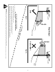
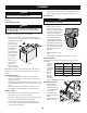
Position Lapbar Drive Control Levers
The lapbar drive control levers can be adjusted up/down and forward/backward for
the operator’s comfort. Three height positions are available and/or levers can be
rotated forward or rearward using the knob.
To adjust the lapbar drive control lever height, proceed as follows:
1. Remove the two carriage
screws (a) and two flange lock
nuts (b) that secure the lapbar
drive control lever (c) to the
upper handle adjuster (d). See
Figure 9.
Note: The multi-tool (if
equipped) can be used to make
this adjustment.
2. Move the lapbar drive control lever
into one of the three available
heights and secure in place with
the carriage screws and flange
lock nuts. See Figure 9.
To adjust the lapbar drive control levers forward/rearward, proceed as follows:
1. Rotate the knob (a) counter-
clockwise to loosen the knob
(a). See Figure 10.
2. Lift and rotate the lapbar drive
control lever into the desired
position.
3. Rotate the knob clockwise to
secure the lapbar drive control
lever into position. See Figure 10.
4. If the lapbars do not line
up after making the knob
adjustment, loosen nuts (b),
align lapbars and retighten
nuts. Once this fine adjustment
is made, the lapbars will align
when using the knob adjustment. See Figure 9.
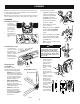
Lower Deck Discharge Chute Deflector
WARNING
Never operate the mower deck without the chute deflector installed and in
the down position.
1. The chute is shipped attached and with a stop bracket holding the chute
upright. The stop bracket must be removed prior
to operating the tractor. See Figure 11.
2. Holding the chute deflector fully upward, remove
the stop bracket:
a. Grasp the bracket (a) from behind the
chute on top of the deck.
b. Lift up slightly to free the bracket from the
notch (b).
c. Pull back to fully remove the bracket.
Setting Deck Wheels
Note: The deck wheels are an anti-scalp feature of the
deck and are not designed to support the weight of the
cutting deck.
1. Move the tractor to a level surface, preferably
pavement.
2. Check tire pressure, adjust, if necessary. See tire side wall for proper tire
pressure.
(b)
(b)
(a)
(a)
(c)
(d)
Figure 9
(a)
Figure 10
c
b
a
Figure 11
3. Make sure the deck is level side-to-side and properly pitched. See the Service
& Maintenance section for deck leveling information and instructions.
4. Place knob in the desired mowing height position and lower the deck.
5. Check the deck wheels for contact or excessive clearance with the surface
below.
Note: The deck wheels should have between ¼” (6.35mm) and ½” (12.7mm)
clearance above the ground.
6. Remove the lock nut (a)
securing one of the front
gauge wheels to the deck.
Remove the shoulder
screw (b), tube spacer (c)
and shoulder spacer (e) to
remove the wheel (d) See
Figure 12.
7. Line up the gauge wheel
with the tube spacer
through the center, and
the shoulder spacer on
the shorter side hub of the
gauge wheel, and position
the assembly inside the
brackets at the desired
height.
Note: Allow a ⁄⁄” (6.35-12.7 mm)clearance between the ground and gauge
wheel.
8. Insert the shoulder screw into the chosen index hole on the front gauge
wheel bracket.
Note: On the left side and right side deck gauge
wheels, the shoulder screw must be installed from
the outside of the tractor inward, through the
square hole on the bracket. On center deck gauge
wheels (if equipped) the shoulder screw side of the
assembly can be installed from either direction. See
Figure 13.
9. Secure with the lock nut previously
removed.
Battery Information
WARNING
California PROPOSITION 65 WARNING: Battery posts, terminals,
and related accessories contain lead and lead compounds, chemicals
known to the State of California to cause cancer and reproductive harm.
Wash hands after handling.
WARNING
Should battery acid accidentally splatter into the eyes or onto the skin,
rinse the affected area immediately with clean cold water. Seek prompt
medical attention.
If acid spills on clothing, first dilute it with clean water, then neutralize
with a solution of ammonia/water or baking soda/water.
NEVER connect (or disconnect) battery charger clips to the battery while
the charger is turned on, as it can cause sparks.
Keep all sources of ignition (cigarettes, matches, lighters) away from the
battery. The gas generated during charging can be combustible.
As a further precaution, only charge the battery in a well ventilated area.
Always shield eyes and protect skin and clothing when working near
batteries.
Batteries contain sulfuric acid and may emit explosive gases. Use extreme
caution when handling batteries. Keep batteries out of the reach of
children.
(a)
(b)
(c)
(d)
(e)
Figure 12
Outer bracket
Inner bracket
Figure 13