Safe Operation Practices • Set-Up • Operation • Maintenance • Service • Troubleshooting • Warranty Operator’s Manual Z-Force L Zero-Turn Tractor WARNING READ AND FOLLOW ALL SAFETY RULES AND INSTRUCTIONS IN THIS MANUAL BEFORE ATTEMPTING TO OPERATE THIS MACHINE. FAILURE TO COMPLY WITH THESE INSTRUCTIONS MAY RESULT IN PERSONAL INJURY. CUB CADET LLC, P.O. BOX 361131 CLEVELAND, OHIO 44136-0019 Printed In USA Form No.
1 To The Owner Thank You Thank you for purchasing a Cub Cadet Zero-Turn Tractor. It was carefully engineered to provide excellent performance when properly operated and maintained. If applicable, the power testing information used to establish the power rating of the engine equipped on this machine can be found at www.opei.org or the engine manufacturer’s web site. Please read this entire manual prior to operating the equipment.
Important Safe Operation Practices 2 WARNING! This symbol points out important safety instructions which, if not followed, could endanger the personal safety and/or property of yourself and others. Read and follow all instructions in this manual before attempting to operate this machine. Failure to comply with these instructions may result in personal injury. When you see this symbol.
12. 13. Stop the blade(s) when crossing gravel drives, walks, or roads and while not cutting grass. 14. Watch for traffic when operating near or crossing roadways. This machine is not intended for use on any public roadway. 15. Do not operate the machine while under the influence of alcohol or drugs. 16. Mow only in daylight or good artificial light. 17. Never carry passengers. 18. Back up slowly. Always look down and behind before and while backing to avoid a back-over accident.
Children 1. Tragic accidents can occur if the operator is not alert to the presence of children. Children are often attracted to the machine and the mowing activity. They do not understand the dangers. Never assume that children will remain where you last saw them. a. b. c. d. e. f. g. 2. Keep children out of the mowing area and in watchful care of a responsible adult other than the operator. Be alert and turn machine off if a child enters the area.
. Mower blades are sharp. Wrap the blade or wear gloves, and use extra caution when servicing them. 7. Keep all nuts, bolts, and screws tight to be sure the equipment is in safe working condition. 8. Never tamper with the safety interlock system or other safety devices. Check their proper operation regularly. 9. After striking a foreign object, stop the engine, disconnect the spark plug wire(s) and ground against the engine. Thoroughly inspect the machine for any damage.
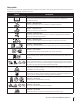
Safety Symbols This page depicts and describes safety symbols that may appear on this product. Read, understand, and follow all instructions on the machine before attempting to assemble and operate. Symbol Description READ THE OPERATOR’S MANUAL(S) Read, understand, and follow all instructions in the manual(s) before attempting to assemble and operate DANGER — ROTATING BLADES Never carry passengers. Never carry children, even with the blades off.
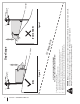
Section 2 — Safe Operation Practices Figure 1 line Figure 2 (TOO STEEP) 15° Slope WARNING! Slopes are a major factor related to tip-over and roll-over accidents which can result in severe injury or death. Do not operate machine on slopes in excess of 15 degrees. All slopes require extra caution. Always mow across the face of slopes, never up and down slopes. To check the slope, proceed as follows: 1. Remove this page and fold along the dashed line. 2.
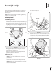
3 Assembly & Set-Up NOTE: This Operator’s Manual covers several models. Tractor features may vary by model. Not all features in this manual are applicable to all tractor models and the tractor depicted may differ from yours. 2. Remove the two shoulder bolts and lock nuts in the seat pan as shown in Figure 3-2. NOTE: All references in this manual to the left or right side and front or back of the tractor are from the operating position only. Exceptions, if any, will be specified.
Position Drive Control levers Lower Deck Discharge Chute Deflector WARNING! Never operate the mower deck without the chute deflector installed and in the down position. The drive control levers of the tractor are lowered for shipping purposes. The hex screws and flat washers that normally secure the control levers in their operating position are in a hardware pack inside your manual bag. The control levers must be repositioned to operate the tractor.
Seats With Arm Rests 1. To adjust the position of the seat, push the seat adjustment lever to the left. See Figure 3-7. 2 Transmission Oil Expansion Reservoir The transmission oil expansion reservoir is connected by hoses to the RH and LH transmission assemblies, and is located behind the seat box. The function of the reservoir is to hold the natural expansion of transmission oil that occurs as the transmission warms up during operation. DO NOT FILL THE RESERVOIR.
Connecting the Battery Cables CALIFORNIA PROPOSITION 65 WARNING! Battery posts, terminals, and related accessories contain lead and lead compounds, chemicals known to the State of California to cause cancer and reproductive harm. Wash hands after handling. CAUTION: When attaching battery cables, always connect the POSITIVE (Red) wire to its terminal first, followed by the NEGATIVE (Black) wire.
4 Controls & Features LH Control Lever RH Control Lever Deck Lift Handle Deck Height Index Throttle Control Choke Control Cup Holder LCD Service Minder & Hour Meter PTO Knob Ignition Switch Module Fuel Tank Cap Fuel Level Window RH Transmission Bypass Rod LH Transmission Bypass Rod NOTE: This Operator’s Manual covers several models. Tractor features may vary by model. Not all features in this manual are applicable to all tractor models and the tractor depicted may differ from yours.
Choke Control Power Take-Off (PTO) Knob The choke control is located on the RH console .The choke control determines the position of the engine choke. Pull the knob out to choke the engine; push the knob in to open the choke. The PTO knob is located on the RH console to the left of the hour meter/indicator panel. Ignition Switch Module WARNING! Never leave a running machine unattended. Always disengage PTO, set parking brake, stop engine and remove key to prevent unintended starting.
LCD Service Minder & Hour Meter When the ignition key is rotated out of the STOP position but not into the START position, the LCD Service Minder and Hour Meter will briefly display the battery voltage, followed by the tractor’s accumulated hours. NOTE: Hours of tractor operation are recorded any time the ignition key is rotated out of the STOP position, regardless of whether the engine is started.
5 Operation General Safety • RECEIVE INSTRUCTION — Entirely read this operator’s manual. Learn to operate this machine SAFELY. Do not risk INJURY or DEATH. Allow only those who have become competent in its usage to operate this tractor. • Before starting the engine or beginning operation, be familiar with the controls. The operator should be in the operator’s seat.
5. Methyl Tertiary Butyl Ether (MTBE) and unleaded gas blends (up to a maximum of 15% MTBE by volume) are approved fuels. Other gasoline/ether blends are not approved. 6. Check the engine oil level. Refer to the Engine Operator’s manual for instructions on checking the engine oil level. 7. Clean the air cleaner element if necessary. 8. Check the tire inflation pressures. See the tire side wall for proper inflation pressures.
Driving the Tractor Using Jumper Cables To Start Engine WARNING! Batteries contain sulfuric acid and WARNING! Avoid sudden starts, excessive speed and sudden stops. produce explosive gasses. Make certain the area is well ventilated, wear gloves and eye protection, and avoid sparks or flames near the battery. If the battery charge is not sufficient to crank the engine, recharge the battery. If a battery charger is unavailable and the tractor must be started, the aid of a booster battery will be necessary.
1. Slowly and evenly move both drive control levers forward. The tractor will start to move forward. See Figure 5-2. Turning the Tractor While Driving Forward WARNING! When reversing the direction of travel, we recommend performing gradual ‘U’ turns where possible. Sharper turns increase the possibility of turf defacement, and could affect control of the tractor. ALWAYS slow the tractor before making sharp turns.
3. The greater the fore-to-aft distance between the two levers, the sharper the tractor will turn. 4. To execute a “pivot turn,” move the turn side drive control lever to the neutral position, while moving the other control lever forward. NOTE: Making a “pivot turn” on grass will greatly increase the potential for defacement of the turf. Turning While Driving Rearward To turn the tractor while driving rearward, move the control levers as necessary so that one lever is forward of the other.
Reverse Caution Mode Executing a Zero Turn WARNING! When executing a zero turn, the tractor MUST BE STOPPED. Executing a zero turn while the tractor is moving can significantly reduce your control of the tractor and will cause severe turf defacement to occur. The REVERSE CAUTION MODE position of the key switch module allows the tractor to be operated in reverse with the blades (PTO) engaged. NOTE: Mowing in reverse is not recommended.
Executing a “Y” Maneuver Driving On Slopes For low traction conditions, follow these procedures for zero turns (the “Y-maneuver”): Refer to the slope gauge in the Safe Operation Section to help determine slopes where you may not operate safely. WARNING! Do not operate on inclines with a slope in excess of 15 degrees (a rise of approximately 2-1⁄2 feet every 10 feet). The tractor could overturn and cause serious injury. To turn clockwise (front of machine moves toward RIGHT) when traveling FORWARD: 1.
Mowing Deck Lift Lever WARNING! Make certain the area to be mowed is free of debris, sticks, stones, wire or other objects that can be thrown by the rotating blades. NOTE: Do not engage the mower deck when lowered in grass. Premature wear and possible failure of the ‘V” belt and PTO clutch will result. Fully raise the deck or move to a non grassy area before engaging the mower deck. 1. Mow across slopes, not up and down. If mowing a slope, start at bottom and work upward to ensure turns are made uphill.
6 Maintenance & Adjustments Maintenance Schedule Before Each use Check Intake Screen/Clean as Needed Check & Clean Engine Cooling Fans for Debris Check Engine Oil Level Check Air Filter for Dirty, Loose or Damaged Parts Clean Transmission Cooling Slots After First 5 Hours Every 10 Hours Every 25 Hours Every 50 Hours P P P P P P P P P P P Grease All Lubrication Points Check Blades/Sharpen or Replace as Needed Check Tire Pressure Lube Front Wheels Check/Clean Underside of Deck Check Deck Level/Pitch L
NOTE: This Operator’s Manual covers several models. Tractor features may vary by model. Not all features in this manual are applicable to all tractor models and the tractor depicted may differ from yours. 4. While holding the free end of the oil drain hose over the oil collection container, unscrew the square head hose plug from the end of the hose. SeeFigure 6-1. Drain the engine oil into the collection container. Maintenance 5. After draining the oil, wipe any residual oil from the oil drain hose.
Cleaning the Transmission Cooling Slots Tires Keep both sides of transmission cooling slots on the frame between the engine and the seat box clear of grass clippings and leaves. Check the tire air pressure after every 50 hours of operation or weekly. Keep the tires inflated to the recommended pressures. Improper inflation will shorten the tire service life. See the tire side wall for proper inflation pressures.
4. Recharge the battery before returning to service. Although the tractor may start, the engine charging system may not fully recharge the battery. Hydrostatic Transmission Your zero turn tractor is equipped with dual integrated hydrostatic pumps/transaxles that are sealed and are maintenance-free. However, this model is equipped with a transmission oil expansion reservoir.
Removing The Tractor From Storage 1. Check the engine oil. 2. Fully charge the battery and inflate the tires to the recommended pressure. 3. Fill the fuel tank with clean, fresh gasoline. 4. Start the engine and allow to idle for a few minutes to ensure engine is operating properly. 5. Drive the tractor without a load to make certain all the tractor systems are functioning properly. Adjustments To adjust the drive control levers forward/rearward, proceed as follows: 1.
Leveling the Deck (Front-To-Rear) 1. NOTE: Check the tractor’s tire pressure before performing any deck leveling adjustments. Refer to Tires for information regarding tire pressure. Always level the deck side-to-side before front to rear. Visually check the distance between the front gauge wheels and the ground. If the gauge wheels are near or touching the ground, they should be raised. If more than 1⁄2” above the ground, they should be lowered. 2.
Drive Control Lever Stop Adjustment When the drive control levers are both fully extended forward to the full-speed position and the tractor drifts left or right, the drive control lever stop adjustment can be adjusted to sync the wheel speeds. To perform the adjustment, proceed as follows: 1. 2. 2. Service the engine as instructed in the separate engine manual. 3.
7 Service Battery Removal Charging the Battery WARNING! Battery posts, terminals and related accessories contain lead and lead compounds. Wash hands after handling. Test and, if necessary, recharge the battery after the tractor has been stored for a period of time. • The battery is located beneath the seat frame. To remove the battery: 1. Remove the hex washer screw securing the battery holddown bracket to the frame. Then flip the battery holddown bracket up to free the battery. See Figure 7-1.
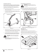
4. Releasing belt tension with the idler pulley: a. Using the deck lift handle, raise the deck to the position that provides the most horizontal run of the belt between the deck idler pulleys and the PTO pulley on the bottom of the engine. See Figure 7-3. 5. Rolling the belt off the PTO pulley: a. Using the deck lift handle, raise the deck to the position that provides the most horizontal run of the belt between the deck idler pulleys and the PTO pulley on the bottom of the engine. b.
6. Locate the LH and RH deck release pins on each side of the deck. Pull the release pins outward and release the deck from the LH and RH deck lift arms. See Figure 7-6. 8. Using the deck lift handle, raise the deck to the position that provides the most horizontal run of the belt between the deck idler pulleys and the PTO pulley on the bottom of the engine. 9.
3. Remove the two idler pulleys by removing the hex screws and flange lock nuts that secure them to the deck and the idler arm. See Figure 7-7. Do not lose any of the hardware when removing the hex screw and flange lock nut. Mower Blade Care WARNING! Before performing any maintenance, place the PTO switch in the “OFF” position, engage the parking brake lever, turn the ignition key to the “OFF” position and remove the key from the switch. Protect your hands by using heavy gloves when handling the blades.
8 Troubleshooting Problem Excessive vibration Uneven cut Mower will not mulch grass (If Equipped w/Mulching Kit) Cause Remedy 1. Cutting blade loose or unbalanced. 1. Tighten blade and spindle. 2. Damaged or bent cutting blade. 2. Replace blade. 1. Deck not leveled properly. 1. Perform side-to-side deck adjustment. 2. Dull blade. 2. Sharpen or replace blade. 3. Uneven tire pressure. 3. Check tire pressure in all four tires. 1. Engine speed too low. 1.
9 Replacement Parts Component Part Number and Description KH-25-132-12-S Spark Plug KH-16-883-04-S1 Air Filter KH-52-050-02-S Oil Filter KH-25-050-22-S1 Fuel Filter 954-05012 954-05013 954-05015 Deck Belt, 48” Deck Deck Belt, 54” Deck Deck Belt, 60” Deck 954-04317A Drive Belt 942-04417 02005017-X 942-04416 02005018-X 942-04415 02005019-X Blades, 48” Xtreme Blades, 48” Blades, 54” Xtreme Blades, 54” Blades, 60” Xtreme Blades, 60” 618-06994 618-06993 618-06076 Deck Spindle, 48” Deck Spindle, 54”
Component Part Number and Description 734-04155 Deck Wheel 925-1707D Battery 751-12179B Gas Cap 746-05133 746-04214 Throttle Control Cable Choke Cable 625-05000 Ignition Key 631-05176 Discharge Chute Assembly 734-1873 934-0255 934-0246A Tire, 20 x 10 x 8.5 Valve Rim Assembly, 8.0 x 6.
10 Attachments & Accessories 38 Part No.
Notes 11 39
Section 11— Notes
Section 11 — Notes 41
FEDERAL and/or CALIFORNIA EMISSION CONTROL WARRANTY STATEMENT YOUR WARRANTY RIGHTS AND OBLIGATIONS MTD Consumer Group Inc, the United States Environmental Protection Agency (EPA), and for those products certified for sale in the state of California, the California Air Resources Board (CARB) are pleased to explain the evaporative emission control system (ECS) warranty on your 2014-2015 small off-road equipment (outdoor equipment).
WARRANTED PARTS: The repair or replacement of any warranted part otherwise eligible for warranty coverage may be excluded from such warranty coverage if MTD Consumer Group Inc demonstrates that the outdoor equipment has been abused, neglected, or improperly maintained, and that such abuse, neglect, or improper maintenance was the direct cause of the need for repair or replacement of the part.
CUB CADET LLC MANUFACTURER’S LIMITED WARRANTY FOR Z-FORCE S/Z-FORCE ZERO-TURN RIDING MOWER IMPORTANT: To obtain warranty coverage owner must present an original proof of purchase and applicable maintenance records to the servicing dealer. Please see the operator’s manual for information on required maintenance and service intervals.