Safe Operation Practices • Set-Up • Operation • Maintenance • Service • Troubleshooting • Warranty Operator’s Manual Z-Force S 60 WARNING READ AND FOLLOW ALL SAFETY RULES AND INSTRUCTIONS IN THIS MANUAL BEFORE ATTEMPTING TO OPERATE THIS MACHINE. FAILURE TO COMPLY WITH THESE INSTRUCTIONS MAY RESULT IN PERSONAL INJURY. CUB CADET LLC, P.O. BOX 361131 CLEVELAND, OHIO 44136-0019 Printed In USA Form No.
1 To The Owner Thank You Thank you for purchasing a Cub Cadet Zero-Turn Tractor. It was carefully engineered to provide excellent performance when properly operated and maintained. Please read this entire manual prior to operating the equipment. It instructs you how to safely and easily set up, operate and maintain your machine. Please be sure that you, and any other persons who will operate the machine, carefully follow the recommended safety practices at all times.
Important Safe Operation Practices 2 WARNING! This symbol points out important safety instructions which, if not followed, could endanger the personal safety and/or property of yourself and others. Read and follow all instructions in this manual before attempting to operate this machine. Failure to comply with these instructions may result in personal injury. When you see this symbol.
12. A missing or damaged discharge cover can cause blade contact or thrown object injuries. 13. Stop the blade(s) when crossing gravel drives, walks, or roads and while not cutting grass. 14. Watch for traffic when operating near or crossing roadways. This machine is not intended for use on any public roadway. Slope Operation Slopes are a major factor related to loss of control and tip-over accidents which can result in severe injury or death. All slopes require extra caution.
Children 1. Tragic accidents can occur if the operator is not alert to the presence of children. Children are often attracted to the machine and the mowing activity. They do not understand the dangers. Never assume that children will remain where you last saw them. a. b. c. d. e. f. g. 2. Service Safe Handling of Gasoline: 1. Keep children out of the mowing area and in watchful care of a responsible adult other than the operator. Be alert and turn machine off if a child enters the area.
3. 4. 5. 6 Periodically check to make sure the blades come to complete stop within approximately (5) five seconds after operating the blade disengagement control. If the blades do not stop within the this time frame, your machine should be serviced professionally by an authorized dealer. Regularly check the safety interlock system for proper function, as described later in this manual.
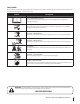
Safety Symbols This page depicts and describes safety symbols that may appear on this product. Read, understand, and follow all instructions on the machine before attempting to assemble and operate. Symbol Description READ THE OPERATOR’S MANUAL(S) Read, understand, and follow all instructions in the manual(s) before attempting to assemble and operate WARNING— ROTATING BLADES Do not put hands or feet near rotating parts or under the cutting deck. Contact with the blade(s) can amputate hands and feet.
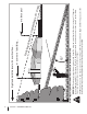
Section 2 — Safe Operation Practices d line dotte (repr esent ing a 15° s lope) or a fence post Operate Z-Force-S zero turn tractors across the face of slopes rather than up and down. Begin with the first pass across the bottom of the slope and turn uphill at the end of each pass whenever possible. WARNING! Do not operate your lawn mower on such slopes. Do not mow on inclines with a slope in excess of 15 degrees (a rise of approximately 2-1/2 feet every 10 feet).
3 Assembly & Set-Up Contents of Crate • • One Lawn Tractor • One Oil Drain Hose • One Z-Force S Tractor Operator’s Manual • One Engine Operator’s Manual One Deck Wash Hose Coupler Tractor Preparation Steering Wheel 1. Remove the upper crating material from the shipping pallet, and cut any bands or tie straps securing the tractor to the pallet. 1. Remove the hardware for attaching the steering wheel from beneath the steering wheel cap.
2. Remove the two shoulder bolts and lock nuts in the seat pan as shown in Fig. 3-3. Adjusting the Seat To adjust the position of the seat, push the seat adjustment lever to the left. Slide the seat forward or rearward to the desired position; then release the adjustment lever. Make sure seat is locked into position before operating the tractor. See Fig. 3-5. Figure 3-3 3. Rotate the seat into position and secure the seat into place with the previously removed shoulder bolts and lock nuts.
2. Install the hitch bracket and muffler mount bracket as shown in Fig. 3-7 and secure with the hex flange screws and flange lock nuts removed in step 1. Connecting the Battery Cables California Proposition 65 Warning! Battery posts, terminals, and related accessories contain lead and lead compounds, chemicals known to the State of California to cause cancer and reproductive harm. Wash hands after handling.
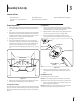
4 Controls & Features Ignition Switch Module Parking Break Engagement Lever Hour Meter/ Indicator Panel PTO Switch Fuel Tank Cap Choke Control Index Plate Deck Lift Pedal Throttle Control Seat Adjustment Lever Drive Pedal Reverse Pedal Figure 4-1 NOTE: References to LEFT, RIGHT, FRONT, and REAR indicate that Ignition Switch Module position on the tractor when facing forward while seated in the operator’s seat. Warning! Never leave a running Deck Lift Pedal machine unattended.
PTO (Power Take-Off ) Switch Indicator Panel Features The PTO switch is located on the LH console to the left of the operator’s seat. Battery Indicator Illuminates and the battery voltage is displayed briefly when the ignition switch it turned to the “ON” position. The PTO switch operates the electric PTO clutch mounted on the bottom of the engine crankshaft. Pull the switch knob upward to engage the PTO clutch, or push the knob downward to disengage the clutch.
Choke Control The choke knob controls the position of the engine choke and is located on the RH console. Pull the knob out to choke the engine; push the knob in to open the choke. Transmission Oil Expansion Reservoir (Not Shown) CHOKE Parking Brake Engagement Lever The parking brake engagement lever is located on the left of the seat box frame, and is used to engage the parking brake.
5 Operation General Safety Before Operating Your Tractor • RECEIVE INSTRUCTION — Entirely read this operator’s manual. Learn to operate this machine SAFELY. Do not risk INJURY or DEATH. Allow only those who have become competent in its usage to operate this tractor. • Before you operate the tractor, study this manual carefully to familiarize yourself with the operation of all the instruments and controls. It has been prepared to help you operate and maintain your tractor efficiently.
Starting the Engine Warning! This tractor is equipped with a safety interlock system designed for the protection of the operator. Do not operate the tractor if any part of the interlock system is malfunctioning. Periodically check the functions of the interlock system for proper operation. Warning! For personal safety, the operator must be sitting in the tractor seat when starting the engine.
Driving The Tractor Reverse Caution Mode WARNING! Avoid sudden starts, excessive speed and sudden stops. The REVERSE CAUTION MODE position of the key switch module allows the tractor to be operated in reverse with the blades (PTO) engaged. NOTE: Mowing in reverse is not recommended. 1. Release the parking brake. Move the throttle lever into the FAST (rabbit) position. 2. To travel FORWARD, slowly press the drive pedal forward until the desired speed is achieved. See Fig. 5-2.
Driving On Slopes • For best results it is recommended that the first two laps be cut with the discharge thrown towards the center. After the first two laps, reverse the direction to throw the discharge to the outside for the balance of cutting. This will give a better appearance to the lawn. • Do NOT attempt to mow heavy brush and weeds or extremely tall grass. Your tractor is designed to mow lawns, NOT clear brush. Keep the blades sharp and replace the blades when worn.
6 Maintenance & Adjustments Maintenance Schedule Before Each use Every 10 Hours P Clean Battery Terminals P Lube Front Caster Wheels and Wheel Spindles Check Engine Cooling Fins for Debris (Clean as Necessary) Every 25 Hours P P Lube Deck Spindles P Lube Pedal Pivot Points Maintenance Warning! Before performing any maintenance or repairs, disengage PTO, set parking brake, stop engine and remove key to prevent unintended starting. 3.
4. If your engine has the oil drain hose setup in Fig. 6-2, see the Oil Drain Hose section below. 2. While holding the free end of the oil drain hose over the oil collection container, unscrew the square head hose plug from the end of the hose. See Fig. 6-2. Drain the engine oil into the collection container. 3. After draining the oil, wipe any residual oil from the oil drain hose. Thread the square head plug into the drain hose fitting and fully tighten the plug. 4.
2. If storing the tractor for 30 days or more: a. To prevent gum deposits from forming inside the engine’s carburetor and causing possible malfunction of the engine, the fuel system must be either completely emptied, or the gasoline must be treated with a stabilizer to prevent deterioration. Warning! Fuel left in the fuel tank deteriorates and will cause serious starting problems. b. c.
1. Drive the tractor to a level, clear spot on your lawn, near enough for your garden hose to reach. Caution: Make certain the tractor’s discharge chute is directed AWAY from your house, garage, parked cars, etc. 1. Disengage the PTO (Blade Engage), set the parking brake and stop the engine. 2. Thread the hose coupler (packaged with your tractor’s Operator’s Manual) onto the end of your garden hose. 3. Attach the hose coupler to the water port on your decks surface. See Fig. 6-4.
4. Tires WARNING! Never exceed the maximum inflation pressure shown on the sidewall of the tire. Refer to the tire sidewall for exact tire manufacturer’s recommended or maximum psi. Do not overinflate. Uneven tire pressure could cause the cutting deck to mow unevenly. Adjustments NOTE: Check the tractor’s tire pressure before performing any deck leveling adjustments. Refer to Tires on page 21 for information regarding tire pressure.
Setting the Deck Wheels Move the tractor on a firm and level surface, preferably pavement, and proceed as follows 1. Select the height position of the cutting deck by placing the deck lift pedal in the normally desired mowing height setting. 2. Check the deck wheels for contact or excessive clearance with the surface below. The deck wheels should have between ¼-½” clearance above the ground. 3. If the deck wheels have excessive clearance or contact with the surface, adjust as follows: a.
7 Service Warning! Before performing any service, place the PTO switch in the “OFF” position, engage the parking brake lever, turn the ignition key to the “OFF” position and remove the key from the switch. • Battery Removal Warning! Battery posts, terminals and related accessories contain lead and lead compounds. Wash hands after handling. A voltmeter or load tester should read 12.6 volts (DC) or higher across the battery terminals. See Fig. 7-2. Voltmeter Reading State of Charge Charging Time 12.
3. Using a 1⁄2” drive in the idler pulley bracket, turn the wrench towards the back of the tractor and slide the belt off the PTO pulley. See Fig. 7-4. Deck Installation Install the deck on the tractor as follows: 1. Place the deck lift pedal in the highest mowing position and secure it by placing the click pin behind the pedal. Refer to Fig. 7-3. 2. Slide the deck under the tractor on the right side of the tractor lining up the deck lift adjustment brackets and the deck lift brackets on the deck.
5. After all four cotter pins are secure, slide the deck forward and hook the deck to the U-rod. Replacing the Deck Belt 6. Route the PTO belt as shown in Fig. 7-8. After routing the belt around the PTO pulley, use a 1⁄2” drive in the idler pulley bracket and turn towards the back of the tractor to finish routing the belt around the idler pulley. 1. Remove the deck from beneath the tractor, (refer to Deck Removal on page 24). 2. Remove the hex washer screws securing the belt covers to the deck. 3.
The blades may be removed as follows. 1. Remove the deck from beneath the tractor, (refer to Deck Removal on page 24) then gently flip the deck over to expose its underside. 2. Use a 3⁄4” wrench to hold the hex nut on top of the spindle assembly when loosening the hex nut securing the blade. See Fig. 7-10. Hex Washer Screw Changing the Spindle Assembly 1. Remove the deck from beneath the tractor, (refer to Deck Removal on page 25). 2.
8 Troubleshooting Problem Excessive vibration Uneven cut Mower will not mulch grass (If Equipped w/Mulching Kit) Cause Remedy 1. Cutting blade loose or unbalanced. 1. Tighten blade and spindle. 2. Damaged or bent cutting blade. 2. Replace blade. 1. Deck not leveled properly. 1. Perform side-to-side deck adjustment. 2. Dull blade. 2. Sharpen or replace blade. 3. Uneven tire pressure. 3. Check tire pressure in all four tires. 1. Engine speed too low. 1.
9 Replacement Parts Component Part Number and Description 759-3336 Spark Plug KH-32-083-06-S Air Filter Element KH-32-083-08-S Pre-Cleaner KH-25-050-22-S Fuel Filter KH-52-050-02-S Oil Filter 30 01005376 Deck Belt 954-04262 PTO Belt 754-04250 Drive Belt 02005019 Mowing Blade 618-04426 Deck Spindle
Component Part Number and Description 634-3159 Deck Wheel 925-1707D Battery 751-11817 Gas Cap 946-1086 Throttle Control Cable 746-04752 Choke Control Cable 925-2054A Ignition Key 01006693 Chute Deflector 634-04295 Wheel Assembly 634-04629 Caster Wheel Assembly Section 9 — Replacement Parts 31
10 Attachments & Accessories 32 Part No.
Notes 11 33
FEDERAL and/or CALIFORNIA EMISSION CONTROL WARRANTY STATEMENT YOUR WARRANTY RIGHTS AND OBLIGATIONS MTD Consumer Group Inc, the United States Environmental Protection Agency (EPA), and, for those products certified for sale in the state of California, the California Air Resources Board (CARB) are pleased to explain the emission (evaporative and/or exhaust) control system (ECS) warranty on your outdoor 2006 and later small off-road spark-ignited engine and equipment (outdoor equipment engine) In California, n
WARRANTED PARTS: The repair or replacement of any warranted part otherwise eligible for warranty coverage may be excluded from such warranty coverage if MTD Consumer Group Inc demonstrates that the outdoor equipment engine has been abused, neglected, or improperly maintained, and that such abuse, neglect, or improper maintenance was the direct cause of the need for repair or replacement of the part.
CUB CADET LLC MANUFACTURER’S LIMITED WARRANTY FOR Z-Force s/Z-Force ZERO-TURN RIDING MOWER IMPORTANT: To obtain warranty coverage owner must present an original proof of purchase and applicable maintenance records to the servicing dealer. Please see the operator’s manual for information on required maintenance and service intervals.