CUb BLIND SPOT DETECTION SYSTEM User Manual & Installation Guide VS-95A043 For Passenger Cars Blind Spot Detection I Lane Change Alert
Contents 1. Precautions ......................................................................................................... 2 2. Introduction ........................................................................................................ 5 2.1 System block 2.2 Product specifications 3. Installation Guide .................................................................................... 6 3.1 Installation diagram 3.2 Package contents 3.3 Installation steps 3.
1Precautions Blind Spot Detection System Before using this device, please read this instruction manual carefully before installing or removing it to ensure that the device is safe to use. The Company shall not be liable for any damage arising from failure to comply with the following matters.
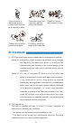
If the connector is dislocated, please replace the connector to its original position. Please do not pull the connector apart by pulling the harness. Connect the connector and terminal tightly. Cut off the excessive length of the cable tie. Please do not pull the harness by force.
NOTE : This equipment has been tested and found to comply with the limits for a Class B digital device, pursuant to part 15 of the FCC Rules. These limits are designed to provide reasonable protection against harmful interference in a residential installation. This equipment generates, uses and can radiate radio frequency energy and, if not installed and used in accordance with the instructions, may cause harmful interference to radio communications.
2 Introduction Blind Spot Detection System Thank you for purchasing this device. The device uses a 77 GHz millimeter-wave radar to detect vehicles coming behind your car. When there is a car getting in the detection zone, the device will provide visual and audible warnings to remind you to pay attention to the car in order to protect the safety of the driver and passengers. If you have any problems while using it, please contact your dealer.
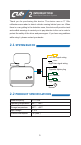
3 Installation Guide Blind Spot Detection System 3-1 Installation diagram Left turn signal Left indicator Buzzer Cigarette lighter plug / IGN WIRING Radar Right turn signal Right indicator 3-2 Package contents No.
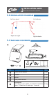
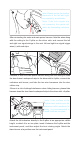
3-3 Installation steps Note: Please ensure that the heat insulation film on the rear windshield does not contain metal components. Please prepare a tape measure, a multimeter and an alcohol pad before installing. Radar installation position diagram 1 Radar 10cm 10cm Center of rear windshield Find a position ±10 cm at the center of the rear windshield's upper edge with a tape measure, and wipe it with an alcohol pad.
4 Note: Please ensure the positive electrode of the left and right turn signals by a multimeter. Note: If the turn signals are not connected, the system will alarm by illuminating indicators only. After connecting the radar and main power harness, hide the wires along with the ceiling to the C-pillar on the driver side, and connect the left and right turn signal wirings to the car's left and right turn signal trigger wires(+) with crab clips.
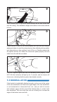
7 Right indicator goes to right side A-pillar through the left side A-pillar and then the ceiling. The installation height and method is the same with the left one. 8 Please ensure to hide all the wires properly into the trims and frame's waterproof strips to avoid the wiring harness from affecting driving safety, and obstructing you from getting in and off the car. Besides please hide the splitter into the trim under the instrument panel properly and use cable ties to fix with the car cables.
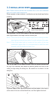
4 User Manual Blind Spot Detection System 4-1 System startup and shut off 4.1.1 System startup When ACC is ON, the indicator will illuminate for 3 seconds, and the buzzer will chime once, indicating that the system starts normally. Note: The system self-tests within 10 seconds after power-on, and using the turn signals or hazard warning lights in this period time would lead to the indicators flashing, which means the system reads the turn signals correctly.
4.2.1 Detection zone BSD 7m LCA 20m LCA 20m BSD 7m 4.2.2 Blind Spot Detection (BSD) When a vehicle approaches your car from behind and enters the detection zone, extending rearward from the radar to approximately 7 m, the corresponding indicator will illuminate. If the corresponding turn signal is ON, the system not only light up the indicator, but also sound an audible alert. Note: If the turn signals are not connected, the system will alarm by illuminating indicators only. BSD 7m 4.2.
If the corresponding turn signal is ON, the system not only light up the indicator, but also sound an audible alert. Note: If the turn signals are not connected, the system will alarm by illuminating indicators only. LCA 20m 4-3 System abnormalities 4.3.1 Malfunction prompts If the system malfunctions, the buzzer will sound an audible alert for 3 seconds for every 10 minutes. and the two indicators will light up until the system returns to normal. 4.3.
Item power on self inspection System Abnormal Status Possible Causes Possible solution The indicator does not light up. Damaged connector or poor contact Re-plug the connector and check if the indicator can light up or not. If it still does not light up, please contact the dealer No sound. Damaged connector or poor contact Re-plug the connector and check if the buzzer can sound or not.
14
www.cubelec.com.tw E-mail: adasinfo@cubelec.com.tw Address : NO.6, LANE 546, SEC.6, changlu RD., fuhsin township, changhua county 50648, taiwan(R.O.C.