AK Series Actuator Driver Manual V1.0.8 1 / 52 https://www.cubemars.
CONTENT Content---------------------------------------------------------------------------------------------------- 2 Notice------------------------------------------------------------------------------------------------------ 4 Feature-----------------------------------------------------------------------------------------------------5 Disclaimer--------------------------------------------------------------------------------------------------5 Version Change Record------------------------------------------
5. Driveboard Communication Protocol and Description------------------------------------------32 5.1 Servo Mode Control and Description--------------------------------------------------------- 32 5.1.1 Duty Cycle Mode--------------------------------------------------------------------------- 34 5.1.2 Current Loop Mode------------------------------------------------------------------------ 34 5.1.3 Current Brake Mode----------------------------------------------------------------------- 35 5.1.
Notice 1. Ensure that the circuit is normal and the interface is correctly connected as required. 2. The driver board will be hot when output, please use it carefully to avoid burns. 3. Please Check whether the parts are in good condition before use. If any parts are missing or aging, please stop using and contact technical support in time. 4. Several optional control modes can’t be switched when driver board is working, and different control mode have different communication protocol.
Feature The AK series actuators’ driver board adopts the driver chip with highperformance, uses the Field Oriented Control (FOC) algorithm, and is equipped with advanced active disturbance rejection control technology to control the speed and angle. It is matched with our modular motor to form a powerful power package. It can be used with CubeMars Tool assistant software for parameter setting and firmware upgrade. Disclaimer Thank you for purchasing the AK series actuators.
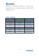
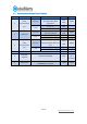
permission, it is not allowed to reproduce in any form. The final interpretation right of the disclaimer belongs to JIANGXI XINTUO ENTERPRISE CO., LTD. Version Change Record Date Version Change content 2021.9.1 Ver. 1.0.0 create version 2021.9.26 Ver.1.0.1 Correct the Can code of 5.3 2021.10.08 Ver.1.0.2 Change code of 5.1 and 5.2 2021.10.29 Ver.1.0.3 Correct data definitions of 5.1,5.2 and 5.3 2021.11.15 Ver.1.0.4 2021.11.24 Ver.1.0.5 UART protocol update of 5.2 2021.11.30 Ver.1.0.
1.Drive Product Information 1.
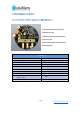
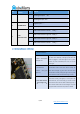
1.2 Drive Interface and Definition 1.2.1 Drive Interface Diagram 1.2.2 The Brand and Model of Drive Interface No. Onboard interface model Brand Wire interface model Brand 1 A1257WR-S-3P CJT A1257H-3P CJT 2 XT30PW-M AMASS XT30UPB-F AMASS 3 A1257WR-S-4P CJT A1257H-4P CJT 1.2.3 Drive Interface pin Definition No. 1 Interface function Serial communication Pin 1 Explain Serial signal ground(GND) 8 / 52 https://www.cubemars.
No. 2 3 Interface function Pin Explain 2 Serial signal output (TX) 3 Serial signal input(RX) 1 Negative pole(-) 2 Positive pole(+) 1 CAN communication low side (CAN_L) 2 CAN communication high side(CAN_H) 3 CAN communication high side(CAN_H) 4 CAN communication low side (CAN_L) POWER INPUT Can communication 1.3 Drive Indicator Definition Indicator definition The power indicator is used to show the power supply of 1.Power indicator(when blue light is on) the driver board.
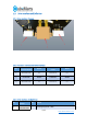
1.4 Main Accessories and Specifications NO.
2. R-link produce information 2.1 Introduction of R-link' appearance&Specifications Specification Rated Voltage 5V Power consumption ≤30mA Size 39.2x29.2x10MM Working Environment temperature -20℃-65℃ Maximum allowable temperature of board 85℃ 11 / 52 https://www.cubemars.
2.2 R-link Interface and Definition No. 1 2 Interface function Communication Interface USB interface Pin Definition 1 CAN communication low side(CAN_L) 2 CAN communication high side(CAN_H) 3 Serial signal input(RX) 4 Serial signal output (TX) 5 Serial signal ground(GND) 1 VBUS 2 D- 3 D+ 4 ID 5 GND 12 / 52 https://www.cubemars.
2.3 R-link Indicator Definition No. 1 2 3 3. Color Definition GREEN The power indicator is used to indicate the power status of the R-link. Under normal circumstances, it will light up green when the power is plugged in. If the green light does not light up when the power is plugged in, please remove the power immediately and never turn on the power again BLUE Serial communication output (TX), always off, flashes when there is data output from the R-link serial port.
4. Instructions for use of the upper computer 4.1 PC interface and instruction A. B. C. D. E. F. G. Home Chinese and English Switching Main page Implement data display Current mode Serial port selection control parameter 14 / 52 https://www.cubemars.
4.1.1 Home 4.1.1.1 waveform display This page supports viewing real-time data feedback and drawing images. Data includes: motor current, temperature, real-time speed, inner encoder position, outer encoder position, high-frequency speed, rotor position, path planning, position deviation, DQ current, etc. 15 / 52 https://www.cubemars.
4.1.1.2 System Setting This page is mainly about changing the hardware limitations of the drive board such as voltage, current, power, temperature, duty ratio, etc. It mainly protects the drive board and motors. ⚠ :Please use it strictly in accordance with the specified voltage, current, power, and temperature. Our company will not bear any legal responsibility if the operation of this product in violation of regulations causes injury to the human body or irreversible damage to the drive board and motor.
This page is mainly about adjusting the parameters of the drive board, including but not limited to current loop Kp-Ki, encoder paranoia, maximum and minimum current, maximum and minimum speed, speed loop Kp-Ki-KD, reduction ratio and other parameters, as well as encoder calibration and motor parameter tuning. ⚠ :Please use it strictly in accordance with the specified voltage, current, power, and temperature.
4.1.1.5 Parameter Save Save the upper computer parameters to the actuator. 4.1.1.6 Export Settings Save the upper computer parameters as two files with the suffixes ".McParams" and to the computer. The ".McParams" file is: The ".AppParams" file is: 18 / 52 https://www.cubemars.
4.1.1.7 Import Settings Upload the parameters of the two files with the suffix ".McParams" and ".AppParams" on the computer to the upper computer. 4.1.1.8 Restore Factory This feature is not currently enabled. 4.1.1.9 Mode Switch This page is mainly about switching the control mode of the drive board, including "guide mode", "servo mode" and "MIT power mode", and update the driver board firmware. 19 / 52 https://www.cubemars.
A).Import firmware area:It can import files with the suffix ".bin" in the computer. B). Firmware update progress bar C). Enter boot mode D). Enter MIT power mode E). Enter servo mode 4.1.1.10 System reset Stop the actuator and reset. 4.1.1.11 About About the version number of the host computer and the official website of the company https://www.cubemars.com/ 20 / 52 https://www.cubemars.
4.2 Driver board calibration After you reinstall the driver board on the motor, or change the line sequence of the motor's three-phase line, or update the firmware, you must calibrate it. After calibration, the motor can be used normally. 4.2.
4.2.2 MIT power mode Confirm that the motor input power is stable, the R-LINK connection is normal, and the motor is in force control mode, after successfully connecting with the host computer, click "Debug Mode" on the "Motion Control" interface, and then input "calibrate" in the input field, Wait for about 30 seconds.
4.3 Control demo 4.3.1 Servo mode 4.3.1.
4.3.1.2 Single loop position velocity mode Confirm that the motor input power is stable, the R-LINK connection is normal, and the motor is in servo mode, after successfully connecting with the host computer, click "single-turn mode" on the "servo control" interface, and after inputting the desired position (there is only one circle at this time, is from 0°to 359°), the desired speed and acceleration, the motor will move at the desired speed until it reaches the desired position. 24 / 52 https://www.
4.3.1.3 Position mode Confirm that the motor input power is stable, the R-LINK connection is normal, and the motor is in servo mode, input the desired position in the "Servo Control" interface after connecting with the host computer successfully, and the motor will reach the desired position at the maximum speed. 25 / 52 https://www.cubemars.
4.3.1.4 Velocity mode Confirm that the motor input power is stable, the R-LINK connection is normal, and the motor is in servo mode, after connecting with the host computer successfully, input the desired speed (±50000ERPM) in the "Servo Control" interface, and the motor will move at the desired speed. 4.3.1.5 Duty cycle mode Confirm that the motor input power is stable, the R-LINK connection is normal, and the motor is in servo mode, input the desired duty ratio(default 0.005-0.
4.3.2 MIT power Mode 4.3.2.1 Position Mode Confirm that the motor input power is stable, the R-LINK connection is normal, and the motor is in force control mode, after connecting with the host computer successfully, input corresponding “CAN ID” in the “Mit Control” interface and then click “RUN”,you can enter the motor mode. The motor will perform position movement (default speed 12000erpm, acceleration 40000erpm) after inputting desired position, KP and KD. 27 / 52 https://www.cubemars.
4.3.2.2 Velocity mode Confirm that the motor input power is stable, R-Link connection is well, and the motor is in force control mode. After the motor is successfully connected with the upper computer, enter the corresponding "CAN ID" on the "Mit Control" interface and click "Enable Control" to enter the motor mode. After the expected speed and KD are input, the motor will running at speed. 28 / 52 https://www.cubemars.
4.3.2.3 Torque mode Confirm that the motor input power is stable, R-Link connection is normal, and the motor is in force control mode. After the motor is successfully connected with the upper computer, enter the corresponding "CAN ID" on the "Mit Control" interface and click "Enable Control" to enter the motor mode. After the expected torque is input, the motor will running accord to the torque. 29 / 52 https://www.cubemars.
/ 52 https://www.cubemars.
4.4 Firmware update 1. Click Open File and select the firmware. The firmware name extension is.bin. 2. Click Bootloader. 3. Click download and wait for the progress bar to reach 100%. Then restart the power supply. 31 / 52 https://www.cubemars.
5. Driver board communication protocol and description 5.
CAN_PACKET_SET_CURRENT_BRAKE, // Current brake mode CAN_PACKET_SET_RPM, //Velocity mode CAN_PACKET_SET_POS, // Position mode CAN_PACKET_SET_ORIGIN_HERE, //Set origin mode CAN_PACKET_SET_POS_SPD, //Position velocity loop mode } CAN_PACKET_ID; void comm_can_transmit_eid(uint32_t id, const uint8_t *data, uint8_t len) { uint8_t i=0; if (len > 8) { len = 8; } CanTxMsg TxMessage; TxMessage.StdId = 0; TxMessage.IDE = CAN_ID_EXT; TxMessage.ExtId = id; TxMessage.RTR = CAN_RTR_DATA; TxMessage.
5.1.1 Duty cycle mode: Duty cycle mode sends data definitions Data bits Data[3] Data[2] Data[1] Data[0] Range 0~0xff 0~0xff 0~0xff 0~0xff Corresponding Duty cycle 25-32 bit Duty cycle 17-24 bit Duty cycle 9-16 bit Duty cycle 1-8 bit variables void comm_can_set_duty(uint8_t controller_id, float duty) { int32_t send_index = 0; uint8_t buffer[4]; buffer_append_int32(buffer, (int32_t)(duty * 100000.
5.1.3 Current Brake Mode Current brake mode sends data definition Data bits Data[3] Data[2] Data[1] Data[0] Range 0~0xff 0~0xff 0~0xff 0~0xff Correspondin Brake current Brake current 17-24 Brake current 9-16 Brake current 1-8 g variables 25-32 bit bit bit bit Among them, the braking current value is of int32 type, and the value 0-60000 represents 0-60A.
5.1.4 Velocity mode Velocity loop simple control block diagram Velocity loop mode sends data definition Data bits Data[3] Data[2] Data[1] Data[0] Range 0~0xff 0~0xff 0~0xff 0~0xff Corresponding Speed 25-32 bit Speed 17-24 bit Speed 9-16 bit Speed 1-8 bit variables Among them, the speed value is int32 type, and the range -100000-100000 represents -100000-100000 electrical speed.
5.1.
means restoring the default zero point (automatic parameter saving); Position loop sending routine void comm_can_set_origin(uint8_t controller_id, uint8_t set_origin_mode) { comm_can_transmit_eid(controller_id | ((uint32_t) CAN_PACKET_SET_ORIGIN_HERE << 8), buffer, send_index); } 5.1.
buffer_append_int16(buffer,spd, & send_index1); buffer_append_int16(buffer,RPA, & send_index1); comm_can_transmit_eid(controller_id | ((uint32_t)CAN_PACKET_SET_POS << 8), buffer, send_index); } 5.2 Servo mode of motor message format 5.2.1 Servo mode CAN upload message protocol In servo mode, motor packets are uploaded in timing mode.
&motor_spd= (float)( spd_int * 10.0f);//motor speed &motor_cur= (float) ( cur_int * 0.01f);//motor current &motor_temp= (rx_message)->Data[6] ;//motor temperature &motor_error= (rx_message)->Data[7] ;//motor error mode } 5.2.
receives the motor feedback once the motor status Example of motor return serial port command:02 49 04 01 66 FC D0 00 00 00 00 00 00 00 00 00 00 00 00 00 00 00 00 00 00 FF FF FF F3 00 F6 00 00 00 00 00 00 00 00 00 00 00 00 00 00 00 00 FF FF FF FF 00 16 D7 AD 00 0A 6F 19 40 7E 00 00 00 00 00 00 00 00 00 00 00 00 00 04 4D 53 03 02 05 16 00 1A B6 03 C9 B5 03 // 02(frame header)+49(Data length)+ 04(Data Frame) + mos temperature(2byte)+motor temperature (2byte)+output current(4byte)+input current(4byte)+Id curre
acquired parameters are determined by the 4 bytes of the data segment. When the corresponding bit is 1, the motor will return the motor parameters of the corresponding bit. When it is 0, this field will be removed.
FAULT_CODE_ENCODER_SPI,// SPI ENCODER FAULT FAULT_CODE_ENCODER_SINCOS_BELOW_MIN_AMPLITUDE,//Encoder overrun FAULT_CODE_ENCODER_SINCOS_ABOVE_MAX_AMPLITUDE,//Encoder overrun FAULT_CODE_FLASH_CORRUPTION,// FLASH FAULT FAULT_CODE_HIGH_OFFSET_CURRENT_SENSOR_1,// Current sampling channel 1 fault FAULT_CODE_HIGH_OFFSET_CURRENT_SENSOR_2,// Current sampling channel 2 fault FAULT_CODE_HIGH_OFFSET_CURRENT_SENSOR_3,// Current sampling channel 1 fault FAULT_CODE_UNBALANCED_CURRENTS,// current unbalance } mc_fault_code;
Handbrake current sending mode example Serial command:02 05 0A 00 00 13 88 00 0E 03 //5A HB current Electrical speed Serial command:02 05 0A FF FF EC 78 68 2E 03 //5A HB current Electrical speed HAND_Brake=(float)buffer_get_int32(data, &ind) / 1000.0 //值为接收 4 位数据/1000.0 Example of Sending Mode of Position Velocity Loop Serial command:02 0D 5B 00 02 BF 20 00 00 13 88 00 00 75 30 A5 AC 03 /* 180 度 转速 5000ERPM 加速度 30000/S 数据段为 位置+ 速度 + 加速度 */ Pos=(float)buffer_get_int32(data, &ind) / 1000.
0x50a5, 0x60c6, 0xd1ad, 0xe1ce, 0xf1ef, 0x72f7, 0x62d6, 0x9339, 0xe3de, 0x2462, 0x3443, 0xa56a, 0xb54b, 0x8528, 0x2672, 0x1611, 0x0630, 0x9719, 0x8738, 0xf7df, 0x78a7, 0x0840, 0x1861, 0x8948, 0x9969, 0xa90a, 0x0a50, 0x3a33, 0x2a12, 0xbb3b, 0xab1a, 0x6ca6, 0x1c41, 0xedae, 0xfd8f, 0x7e97, 0x6eb6, 0x5ed5, 0xefbe, 0xdfdd, 0xcffc, 0xb1ca, 0xa1eb, 0xd10c, 0x20e3, 0x5004, 0x4025, 0xc33d, 0xd31c, 0xe37f, 0x5214, 0x6277, 0x7256, 0xd52c, 0xc50d, 0x34e2, 0x4405, 0xa7db, 0xb7fa, 0x26d3, 0x36f2, 0x0691, 0xc96d, 0x70e7,
0xf90e, 0xe92f, 0x7806, 0x6827, 0x18c0, 0xfb1e, 0x8bf9, 0x9bd8, 0x0af1, 0x1ad0, 0x2ab3, 0xad8b, 0x9de8, 0x8dc9, 0x1ce0, 0x0cc1, 0xef1f, 0x9ff8, 0x6e17, 0x7e36, }; 0x99c8, 0x89e9, 0xb98a, 0xa9ab, 0x5844, 0x4865, 0x08e1, 0x3882, 0x28a3, 0xcb7d, 0xdb5c, 0xeb3f, 0xabbb, 0xbb9a, 0x4a75, 0x5a54, 0x6a37, 0x7a16, 0x3a92, 0xfd2e, 0xed0f, 0xdd6c, 0xcd4d, 0xbdaa, 0x7c26, 0x6c07, 0x5c64, 0x4c45, 0x3ca2, 0x2c83, 0xff3e, 0xcf5d, 0xdf7c, 0xaf9b, 0xbfba, 0x8fd9, 0x4e55, 0x5e74, 0x2e93
//int64 数据位整理 void buffer_append_int64(uint8_t* buffer, int64_t number, int32_t *index) { buffer[(*index)++] = number >> 56; buffer[(*index)++] = number >> 48; buffer[(*index)++] = number >> 40; buffer[(*index)++] = number >> 32; buffer[(*index)++] = number >> 24; buffer[(*index)++] = number >> 16; buffer[(*index)++] = number >> 8; buffer[(*index)++] = number; } //uint64 数据位整理 void buffer_append_uint64(uint8_t* buffer, uint64_t number, int32_t *index) { buffer[(*index)++] = number >> 56; buffer[(*index)++]
handler_states[handler_num].tx_buffer[b_ind++] = 2; handler_states[handler_num].tx_buffer[b_ind++] = len; } else { handler_states[handler_num].tx_buffer[b_ind++] = 3; handler_states[handler_num].tx_buffer[b_ind++] = len >> 8; handler_states[handler_num].tx_buffer[b_ind++] = len & 0xFF; } memcpy(handler_states[handler_num].tx_buffer + b_ind, data, len); b_ind += len; crc = crc16(data, len); handler_states[handler_num].tx_buffer[b_ind++] = (uint8_t)(crc >> 8); handler_states[handler_num].
Data fields DATA[0] DATA[1] DATA[2] DATA[3] Data bits 7-0 7-0 7-0 7-4 3-0 The data content Motor position 8 bit high Motor position 8 bit low Motor speed 8 bit high Motor speed 4 bit low KP value 4 bit high Data fields DATA[4] DATA[5] Data bits 7-0 7-0 7-4 3-0 0-7 The data content KP value 8 bit low KD value 8 bit high KD value 4 bit low Current value 4 bit high Current value 8 bit low DATA[6] DATA[7] MIT power mode driver board sending data definition Identifier: 0X00+ Dri
Position -12.5f-12.5f (rad) Speed (rad/s) Torque (N.M) -50.0f-50.0f -45.0f-45.0f -50.0f-50.0f -76.0f-76.0f -50.0f-50.0f -65.0f-65.0f -15.0f-15.0f -25.0f-25.0f -12.0f-12.0f -18.0f-18.0f Kp range 0-500 Kd range 0-5 -8.0f-8.0f -144.0f-144 Sends routine code void pack_cmd(CANMessage * msg, float p_des, float v_des, float kp, float kd, float t_ff){ /// limit data to be within bounds /// float P_MIN =-95.5; float P_MAX =95.
msg->data[4] = kp_int&0xFF; // KP 8 bit lower msg->data[5] = kd_int>>4; // Kd 8 bit higher msg->data[6] = ((kd_int&0xF)<<4)|(kp_int>>8); // msg->data[7] = t_int&0xff; KP 4 bit lower torque 4 bit higher // torque 4 bit lower } When sending packets, all the numbers should be converted into integer numbers by the following functions and then sent to the motor.
/// converts unsigned int to float, given range and number of bits /// float span = x_max - x_min; float offset = x_min; return ((float)x_int)*span/((float)((1<