
- Motorola Digital Return Transmitter Installation Sheet


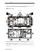
Table Of Contents
- Installation Sheet
- Related Documentation
- Document Conventions
- Before You Begin
- Installing the SG2-DRT-3X in the SG2440 Node
- Installing the SG2-DRT-3X in the SG2440 Node in a 1X or 2X Configuration
- Installing the SG2-DRT-3X in the SG2000 Node
- Installing the SG2-DRT-3X in the SG2000 Node in a 1X or 2X Configuration
- Specifications
- SG2-DRT-3X DWDM Models
- SG2-DRT-3X CWDM Models
- If You Need Help
- Caution/Compliance
- Declarations of Conformity
- Copyright
- Back Cover
STARLINE 7
SG2-DRT-3X Installation Sheet
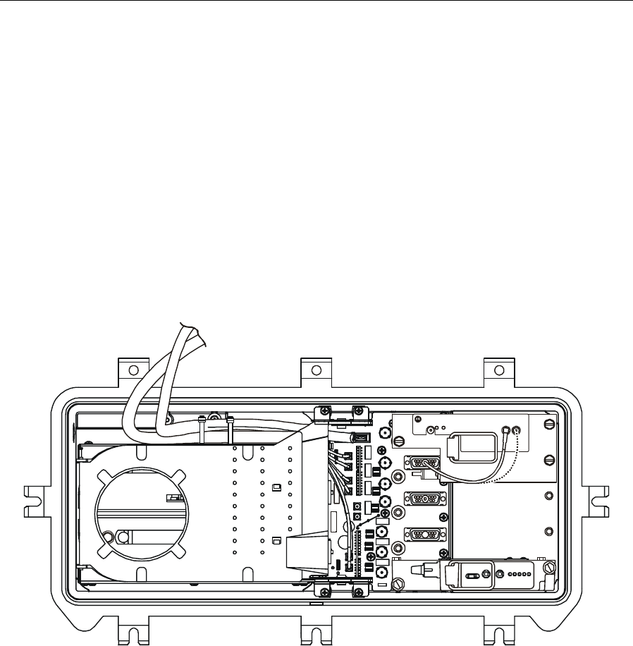
Installing the SG2-DRT-3X in the SG2440 Node in a 1X or 2X Configuration
The SG2-DRT-3X transmitter can operate with three data streams. If you install the
SG2-DRT-3X in an SG2440 that will remain a combined (1X) or split (2X) return, an additional
cable is provided to properly load the transmitter.
To properly cable the SG2-DRT-3X for a combined or split return:
1 Verify that the SG2440 return configuration plug-in board is either a redundant (1X) or a
split (2X) model.
2 Insert the provided cable from the redundant transmitters’ D-subconnector into RF INPUT A
or
INPUT B on the SG2-DRT-3X as illustrated in Figure 7:
Figure 7
SG2-DRT-3X cabling for combined configuration
3 Change the 15 dB JXP pad at the XMTR A location to a 5 dB JXP.
Installing the SG2-DRT-3X in the SG2000 Node
You can equip the SG2000 with a combined or a split-return path module and still be compatible
with the SG2-DRT-3X.
On SG2000 nodes equipped with an SG2-RPM/C, you can select any two RF ports for
segmentation. The two remaining ports will automatically be combined and put on the
D subconnector beneath the double-wide transmitter.
On SG2000 nodes equipped with an SG2-RPM/S only, you can segment RF ports 1 and 3. Ports
2 and 4 are combined and are automatically put on the D subconnector.
The segmented inputs occupy the ICS plug-in location. If equipped, ICS functionality will be lost
on these two ports.
When the node is equipped with a transponder for status monitoring, Port 1 cannot be segmented
as the ICS location is before the transponder output.