Cat. No. 01021819 Rev.
Attention Culligan Customer: Your local independently operated Culligan dealer employs trained service and maintenance personnel who are experienced in the installation, function and repair of Culligan equipment. This publication is written specifically for these individuals and is intended for their use. We encourage Culligan users to learn about Culligan products, but we believe that product knowledge is best obtained by consulting with your Culligan dealer.
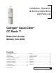
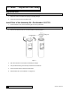
Installation, Operation & Service Instructions with Parts List Culligan® Aqua-Cleer® CC Basic™ Bottle-less Cooler Models from 2008 Contents Key Pre-Delivery Activities.................................................ii Warranty........................................................................... 15 Introduction........................................................................ 1 CC Basic™ Parts List...................................................... 16 Safety Information.................
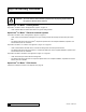
Key Pre-Delivery Activities CAUTION! The cooler and the water treatment equipment must be properly prepared before the system is delivered to the customer. Aqua-Cleer® CC Basic™ Filter Systems Aqua-Cleer® CC Basic™ Filter—see Appendix A, Figure 5, on page 18. • Uses: sediment filter and carbon block filter in two (2) E-Z Change heads. Aqua-Cleer® CC Basic™ Reverse Osmosis Systems Aqua-Cleer® CC Basic™ RO—see Appendix B, Figure 8 on page 19.
Pre-Delivery Activity: Prepare and Flush Water Treatment Components CAUTION! All RO Membranes will require a 24-hour flush to drain. All flushing of membranes and filters must be done with chlorine-free, filtered, softened water.
This page intentionally left blank. iv Culligan® Aqua-Cleer® CC Basic™ iv Cat. No.
Introduction The Culligan Aqua-Cleer® CC Basic™ system provides an economical solution to point-of-use water treatment systems in the marketplace. Unlike a bottled water cooler, incoming tap water is treated as it is needed, so the water is always fresh and great tasting. Best of all, there are no bottles to change and the supply is unlimited.
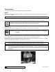
Safe Practices Throughout this manual there are paragraphs set off by special headings. Notice Notice is used to emphasize installation, operation or maintenance information which is important, but does not present any hazard. For example, NOTICE The nipple must extend no more than 1 inch above the cover plate. Caution Caution is used when failure to follow directions could result in damage to equipment or property. For example, CAUTION! Disassembly while under water pressure can result in flooding.
Safety Information Electrical Safety • Only connect the power cord to a 120V properly grounded outlet. • Never pull the power plug from the outlet with a wet hand or allow the plug to get wet. • Keep the power cord out of heavy traffic areas. • To avoid a fire hazard, never put the power cord under rugs, near radiators, stoves or heaters. • Do not use a damaged power cord or plug. If the power cord is damaged, a qualified service technician must replace it.
CC Basic™ Inspection and Setup Inspect the Unit NOTE All preparation work should be done in a clean area. A separate room is recommended. 1. Inspect the carton for evidence of shipping or handling damage. 2. Unpack the unit and inspect the plastic parts. Install Point of Use Assembly Kit—Part Number 01017703 1. NOTE 2. On the CC Basic™ unit, remove the locking pin from the Crystal Guard. May require the use of a tool to remove pin.
Close Figure 2. 7. Position the ¼" tubing from the POU kit so that it exits from the rear of the cooler (Figure 3). Figure 3. 8. After installation of the POU kit, the RESET indicator should be located towards the rear of the unit (Figure 4). Cat. No.
Slide to reset After installation of the POU assembly, the reset indicator should be located towards the rear of the cooler Figure 4. Point of Use Kit Indicator Function The POU Kit is designed with two floats. The lower float shuts off the feed water to the reservoir when it lifts. The upper float is a safety float.
CAUTION! The unit is now live. Take suitable safety precautions. 8. Allow 45 minutes to reach full Hot and Cold temperatures. 9. Flush 1-2 gallons (4-8 liters) through each faucet. 10. Verify lower float allows filling and that the upper float will trip the indicator to RED. 11. Turn OFF the Hot tank and the feed water. 12. Unplug and drain the unit. 13. Remove the POU kit and Baffle Cup. 14. Add 1 tablespoon of liquid chlorine beach (5¼% sodium hypochlorite) to one gallon of RO water. 15.
Installing the CC Basic™ NOTE All personnel should be aware of company requirements for their own cleanliness and hygiene when installing, servicing or sanitizing a unit NOTE I f the treatment components have remained in the unit for more than 24 hours since they were flushed and transported to a customer location, it is highly recommended that they get flushed to the drain before installing. Install a pressure regulator, if needed, on the incoming water supply line, set to 40-45 psi.
9. Verify that the compressor and heater are both working. This is best accomplished by placing a hand on top of the compressor to feel for vibration, and by dispensing water from the hot tank (after five minutes) noting a temperature increase in the water. 10. T aste the water. Check the unit is clean and functions to the customer’s satisfaction. If you are not satisfied with the quality of the water, check the filters and flush additional water through the unit. 11.
Sanitizing the CC Basic™ NOTE The CC Basic™ model must be sanitized every 12 months, when taste concerns arise, or after boilwater alerts are lifted. Units in dusty or high-use locations may need more frequent servicing. All personnel should be aware of company requirements for their own cleanliness and hygiene when servicing and sanitizing a unit. Latex gloves must be used when handling the filters, UV bulb, quartz sleeve or any components that have contact with the drinking water.
Descaling the CC Basic™ CC Basic™ units using an RO configuration should rarely need to be descaled. A unit with the hot water option may require removing any calcium build-up inside the hot tank, depending on local water conditions and the type of water treatment. All personnel should be aware of company requirements for their own cleanliness and hygiene when servicing and sanitizing a unit.
10. Slowly turn ON the feed water supply and refill the unit. 11. Drain the Hot tank and continue to flush for another five minutes. 12. Check that no food coloring remains in the rinse water. 13. Turn OFF the feed water and drain the unit completely. Flush and Return the Unit to Service 1. Replace the Baffle Cup and POU kit. 2. Make sure the indicator is in the GREEN position. 3. Turn ON the feed water and refill the unit. 4. Refill the unit with fresh water from the water treatment system. 5.
Troubleshooting NOTE Fault finding must only be carried out by trained personnel. Symptom Possible Cause NO FLOW OF WATER Solution 1. Make sure that there is a water supply to the unit and that it is turned on. 2. If an anti-flood or leak detection device is installed, please check and reset if necessary. 3. For units with EZ heads, ensure that the filter is twisted all the way into the head; otherwise the valve inside the filter head will not be opened. 4.
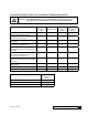
Technical Specifications Item Width/Depth/Height Specification 12.4"x12.8"x38.8" (315mmx325mmx985 mm) Water Connection 1/4" Tubing Cold Tank Capacity 0.9 Gallons (3.5 Liters) Hot Tank Capacity 1.2 Gallons (4.5 Liters) Hot Tank Temperature 167F to 198F(75C to 99C) Recommended Service Pressure 40-45 PSI (3.1 Bar) Maximum Service Pressure 50 PSI (3.4 Bar) Rated Service Flow 0.5 GPM (1.89 LPM) Temperature Rating 50-100 F (10 - 37C) Refrigerant R134a Refrigerant Charge 1.0 Oz (28.
Warranty Limited Warranty for the CULLIGAN® Aqua-Cleer® CC Basic™ Water Treatment System Culligan International Company (CULLIGAN) warrants the water cooler, when installed and operated in accordance with the installation instructions, against defects in material and workmanship under normal use as follows: Three (3) years from the date of installation or 42 months from date of shipment from the factory, whichever occurs first, CULLIGAN at their option will repair or replace any defective parts.
Appendix E Inspection and Setup Procedures Inspect the Unit NOTE All preparation work should be done in a clean area. A separate room is recommended. 1. Inspect the carton for evidence of shipping or handling damage. 2. Unpack the unit and inspect the plastic parts. Install Point of Use Assembly Kit – Part Number 01017703 1. NOTE 2. On the CC Basic™ unit, remove the locking pin from the Crystal Guard. May require the use of a tool to remove pin.
Close Figure 19. 7. Position the ¼” tubing from the POU kit so that it exits from the rear of the cooler (Figure 20). Figure 20. 8. 30 Culligan® Aqua-Cleer® CC Basic™ 30 Cat. No.
9. After installation of the POU kit, the RESET indicator should be located towards the rear of the unit (Figure 21). Slide to reset After installation of the POU assembly, the reset indicator should be located towards the rear of the cooler Figure 21. Point of Use Kit Indicator Function The POU Kit is designed with two floats. The lower float shuts off the feed water to the reservoir when it lifts. The upper float is a safety float.
7. Plug in the unit and turn ON the Hot tank switch. CAUTION! The unit is now live. Take suitable safety precautions. 8. Allow 45 minutes to reach full Hot and Cold temperatures. 9. Flush 1-2 gallons (4-8 liters) through each faucet. 10. Verify lower float allows filling and that the upper float will trip the indicator to RED. 11. Turn OFF the Hot tank and the feed water. 12. Unplug and drain the unit. 13. Remove the POU kit and Baffle Cup. 14.
Cat. No.