Cat. No. 01-8819-48 Revised 1/96 CULLIGAN MARK 10 AUTOMATIC WATER CONDITIONER Installation/Operating Instructions ® Models from 1995 WARNING: IF INCORRECTLY INSTALLED, OPERATED OR MAINTAINED, THIS PRODUCT CAN CAUSE SEVERE INJURY. THOSE WHO INSTALL, OPERATE, OR MAINTAIN THIS PRODUCT SHOULD BE TRAINED IN ITS PROPER USE, WARNED OF ITS DANGERS, AND SHOULD READ THE ENTIRE MANUAL BEFORE ATTEMPTING TO INSTALL, OPERATE OR MAINTAIN THIS PRODUCT.
Attention Culligan Customer: The installation, service and maintenance of this equipment should be rendered by a qualified and trained service technician. Your local independently operated Culligan dealer employs trained service and maintenance personnel who are experienced in the installation, function and repair of Culligan equipment. This publication is written specifically for these individuals and is intended for their use.
CULLIGAN MARK 10 AUTOMATIC WATER CONDITIONERS Installation/Operating Instructions ® Models from 1995 Table of Contents Specifications ........................................................... 2 Preparation ............................................................... 3 Installation ................................................................ 5 Settings .................................................................... 9 Start-Up Procedure ................................................
Specifications Culligan® Mark 10 Automatic Water Conditioners with Auto Clock or Soft-Minder® Meter Control Valve Overall Conditioner Height Media Tank Dimensions (Dia x Ht) Salt Storage Tank Dimensions Exchange Media, Type and Quantity Underbedding Type and Quantity Exchange Capacity @ Salt Dosage Per Recharge1 Freeboard to Media2 Salt Storage Capacity Rated Service Flow @ Pressure Drop Total Hardness, Maximum Total Iron, Maximum Hardness to Iron Ratio, Minimum4 Operating Pressure Operating Temperature E
Preparation COMPONENT DESCRIPTION The water conditioner is shipped from the factory in one carton. Remove all components and inspect them before starting installation. Control Valve Assembly - Includes the 5- cycle regeneration control valve and electronic timer assembly. A small parts package contains installation hardware and consumer literature, including an Owner’s Guide and warranty policy.
LOCATION NOTICE: Most codes require an anti-siphon device or airgap. Space requirements - Allow 6-12 inches (15-30 cm) behind the unit for plumbing and drain lines and 4 feet (1.3 meters) above for service access and filling the salt container. Electrical facilities - A 6-foot grounded cord is provided. The customer should provide a 3-prong grounded receptacle, preferably one not controlled by a switch that can be turned off accidentally. Observe local electrical codes.
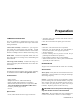
Installation PLACEMENT BRINE CHAMBER ASSEMBLY Refer to Fig. 1 • Remove the nut and screw from the brine chamber housing. • Set the media tank on a solid, level surface near water, drain and electrical facilities. Place the outlet (black coupling) of the tank on the left. • Locate the hole in the recess of the brine tank. Place the screw through this hole. • Set the brine system on a flat, smooth, solid surface as near the media tank as possible. • Line up the hole in the brine chamber with the screw.
• Place brine valve into the chamber. The top of the valve should rest within the groove of the brine chamber. CAUTION: Close the inlet supply line and relieve system pressure before cutting into the plumbing! Flooding could result! MOUNT THE CONTROL VALVE See Fig. 2. • Remove and discard the protective covers on the tank couplings. CAUTION: When making sweat connections, remove all plastic and rubber components which contact brass or copper. Damage to these components may result otherwise.
port of the control. A pair of elongated bolts are packaged with the meter to hold the bypass valve to the back plate of the control. Lubricate all o-rings with silicon lubricant. drain line length and height limitations, and to Fig. 6. SWEAT ADAPTOR INSTALLATION • Route a length of 1/2" drain line from the drain elbow to the drain. The seat adaptors use a snap ring to hold them to the backplate of the control valve. The back plate will need to be removed from the valve for this connection.
• Locate the 1/2" hole in the lower right hand corner of the timer plate. • Slip the meter cable through the hole and toward the circuit board. • Connect the lead to the circuit board at the upper most portion of the lower set of terminal pins. Make sure the cord lays across the circuit board. • Locate the strain relief bushing in the parts pack. Place it on the cable at the point of entry to the rear of the timer plate and push it into the hole. FIG.
Settings Before the unit can be recharged and put into service, several settings must be made. BACKWASH Backwash, the first step in the recharge cycle, expands and loosens the resin bed, and flushes away accumulated turbidity. The backwash interval is preset at the factory for 10 minutes which is adequate for most water supplies. It is adjustable, however, for 5 to 30 minutes. It is recommended that backwash last just long enough so that the effluent from the drain line is clear.
FIG. 8 TIME OF DAY Upon completing the installation, the timer must be set to the correct time of day. Time of day must also be reset after any kind of power interruption, such as that caused by an electrical storm. See Fig. 8. 1. Determine the correct time of day. 2. Grasp the gear (F) and lift straight up (the white time-ofday dial will lift with it). Rotate the dial until the correct time of day lines up with the pointer (G). The dial is springloaded and will return to its position when released.
GALLONS SETTING (Soft-Minder® Models Only) Determine the daily water use for the household. Usually 75-100 gallons per day per person is adequate. Using Tables 2A and 2B, locate the hardness range for your water supply. Move down the column and locate the gallons setting and salt dosage which best suits the application. Usually two to three days between regenerations yields the best results. Allow for one half to one days water usage as reserve capacity. Set the salt dosage per the instructions on page 10.
TABLE 3 - A DIMENSION CHART Salt Dosage (Pounds) 3 4 5 6 7 8 9 10 11 12 13 14 15 16 17 18 19 20 250 lb. Brine Tank A Dimension inches (mm) 3-1/4 4-5/8 6 7-3/8 8-3/4 9-1/4 11-5/8 12-7/8 14-1/2 15-3/4 17-1/4 18-1/2 19-7/8 21-1/4 22-3/4 24-1/2 25-1/2 26-7/8 TABLE 4 - REGENERATION SCHEDULE 375 lb.
TABLE 5B - CULLIGAN® MARK 10, 12" MODEL SALT DOSAGE - FREQUENCY Total Water Hardness In Grains Per Gallon (mg/L) *Persons in Household 0-10 11-20 21-30 31-40 41-50 51-60 61-70 71-80 81-90 91-100 Gallons (liters) (0-170) (171-340) (341-515) (516-685) (686-855) (856-1025) (1026-1200) (1201-1370) (1371-1540) (1541-1700) of Water Per Day 2 9 UNIT IS OVERSIZED USE MARK 10, 9" 3 4 6 6 5 6 7 8 7 5 8 5 9 6 10 7 7 8 7 9 11 13 15 20 1 2 2 2 2 2 2 6 6 5 6 6 8 9 12 8 12 20 3 3 3 3 3 3 6 9 6 6 6 7 8 1
Start-Up Procedure NOTICE: A sanitizing agent has been added to the conditioner tank at the factory. This sanitizing agent must be flushed out before the unit is placed into service by initiating a recharge using the steps outlined below. 1. With the timer in the service position, connect the threewire power cord to an appropriate grounded electrical outlet. If a three-wire outlet is not available, purchase a “three-prong to two-prong adapter” from your local hardware store.
Sanitizing Procedure A water softener in daily use on a potable water supply generally requires no special attention other than keeping the salt tank filled. Occasionally, however, a unit may require sanitation under one of the following conditions: • The unit has stood idle for a week or more (the premises vacant or the residents on vacation). • On private supplies, the appearance of off-tastes and odors, particularly if musty or “rotten egg” (caused by harmless sulfate-reducing bacteria).