Cat. No. 01020401 Rev.
Attention Culligan Customer: The installation, service and maintenance of this equipment should be rendered by a qualified and trained service technician. Your local independently operated Culligan dealer employs trained service and maintenance personnel who are experienced in the installation, function and repair of Culligan equipment. This publication is written specifically for these individuals and is intended for their use.
Installation, Operation and Service Instructions with Parts List Culligan Medallist Series® Automatic Water Conditioner Models from 2007 Table of Contents Page Important Safety Information.............................................. 2 Introduction......................................................................... 4 Performance Specifications................................................ 5 Preparation......................................................................... 6 Basic Principles...
Introduction The Culligan Medallist Series™ 8” Water Softeners are tested and certified by WQA against NSF/ANSI Standard 44 for the effective reduction of hardness (calcium and magnesium) and barium/radium as verified and substantiated by test data. The Culligan Medallist Plus Series™ 30, 45 and 60 Water Softeners are tested and certified by WQA against NSF/ANSI Standard 44 for the effective reduction of hardness (calcium and magnesium) and barium/radium as verified and substantiated by test data.
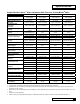
Specifications Culligan Medallist Series™ Water Conditioner With Timeclock Or Soft-Minder® Meter Control Valve Type Overall Conditioner Height Media Tank Dimensions (Dia. x Ht.) Salt Storage Tank Dimensions (Dia. x Ht.
Preparation Component Description The water conditioner is shipped from the factory in a minimum of three cartons. Remove all components from their cartons and inspect them before starting installation. Control Valve Assembly - Includes the 5-cycle regeneration control valve and the Accusoft® Microprocessor. A small parts pack will contain additional installation hardware. An Owner’s Guide is included.
Application Water quality - Verify that raw water hardness and iron are within limits. Note the hardness for setting the salt dosage and recharge frequency. Iron - Iron is a common water problem. The chemical/physical nature of iron found in natural water supplies is exhibited in four general types. 1. Dissolved Iron - Also called ferrous or “clear water” iron.
Location Space requirements - Allow 6-12 inches (15-30 cm) behind the unit for plumbing and drain lines and 4 feet (1.3 meters) above for service access and filling the salt container. Floor surface - Choose an area with solid, level floor free of bumps or irregularities. Bumps, cracks, stones and other irregularities can cause the salt storage tank bottom to crack when filled with salt and water.
Basic Principles Terms Brine - A solution of water and salt used to regenerate the resin Distributor - A pipe with slits that allows the water to enter and leave inside the media tank Media - The underbedding and resin the media tank holds Regenerate - A process where the resin once exhausted of its softening capabilities is revitalized to soften again Resin - The actual material that softens hard water, shaped like little beads Underbedding - A gravel mixture that keeps the resin from entering the distribu
What Is Hard Water? Water is said to be hard when it carries too high a concentration of calcium and magnesium. Acceptable water hardness levels will vary depending on the application. How Does It Work? The components of dissolved minerals are called ions. They carry either a positive or negative charge. Hardness ions of minerals dissolved in water carry a positive charge. These positively charged ions (cations) are attracted to a synthetic softening material called ion exchange resin.
Flow Diagram Service Refer to Figure 3 Raw water is allowed in the inlet to the top of the tank. The water is run through the resin up the manifold to the outlet. The water to the outlet should be soft if the system is operating properly.
Backwash Refer to Fig. 4 Raw water is directed down the center of the manifold, up through the resin, out the top of the tank to drain. The water to drain should be hard.
Regenerant Draw Refer to Fig. 5 Raw water is directed from the inlet through the nozzle and into the throat. A vacuum is created and concentrated brine is educted (drawn). The raw water and concentrated brine combine, enter the mineral tank, and pass through the resin, up the manifold and to the drain. Once all of the brine has been educted and the brine valve seats, the unit goes into slow rinse. Hard water is allowed to service during regeneration.
Slow Rinse Refer to Fig. 6 Raw water is directed from the inlet through the nozzle and into the throat. A vacuum is created but the brine valve has seated, so no brine is educted. The raw water enters the mineral tank, passes through the resin, up the manifold and to the drain. Hard water is allowed to service during regeneration.
Fast Rinse / Refill Refer to Figure 7 Raw water is directed from the inlet, through the eductor and inlet to the top of tank, down the resin, up the manifold, out to drain and brine line until the correct amount of water is in the brine tank. Hard water is allowed to service during regeneration.
Controller Features Control The Culligan Medallist Series™ water softener. It can be programmed as either a time clock or Soft-Minder® meter model. Each model has its own programming parameters which can be set to control the operation and regeneration of the system. These functions are outlined in Table 1. Table 1 Function Time Clock Soft-Minder Meter Time of Day YES YES Time of Regen. YES YES Salt Dosage YES YES Backwash Time YES YES Brine Rinse Time YES YES Regen.
Circuit Board Refer to Figure 8 for all circuit board connections. Power terminals are located along the side edge of the circuit board. The connection marked ‘MAIN’ is for the main wire harness. The Soft-Minder connection is located in the upper left side of the board. Next to the meter connection is a connection marked ‘BATT’, which is for the optional battery back-up. All terminals are clearly marked to ease installation.
Regeneration There are several conditions that will cause the control to trip a regeneration. The “REG” enunciator will light when the control has signaled for a regeneration. The “REG” enunciator will flash while the control is in regeneration. The following are conditions that will call for regeneration, assuming “dip 2” has been set to “DEL”: 1. When the Soft-Minder meter has recorded the passage of a predetermined number or gallons 2. When the time clock has counted past the set number of days. 3.
Installation Placement Refer to Figure 9 for system placement. • Set the media tank on a solid, level surface near water, drain and electrical facilities. Place the outlet (black coupling) of the tank on the left. • Set the brine system on a flat, smooth, solid surface as near the media tank as possible. Figure 9 Mount The Control Valve - 3/4” Control See figure 10 for a visual on mounting the control valve to the tank.
Mount The Control Valve - 1” Control See Figure 11 for a visual on mounting the control valve to the tank. • Assemble the o-rings, located in the parts pack, to the tank adapter. • The valve adapter o-ring sits on the first step on the adapter. See Figure 12. Note: Do not push the top o-ring down to the flange surface on the adapter. Note: The larger of the two o-rings in the parts part goes between the adapter and the valve, do not stretch the smaller o-ring onto the top of the tank adapter.
Eductor Nozzle Replacement: • Remove the three screws on the eductor cap and remove the cap. • Remove the eductor assembly. • Remove the eductor screen from the assembly • Remove the blue nozzle and replace it with the beige nozzle. Make sure to put the o-ring on the beige nozzle. • Reverse the procedure to reassemble. To prevent leaks, ensure that the gasket is in the proper position. Backwash Flow Control Replacement: • Remove the drain clip and pull the drain elbow straight off.
Bypass Valve Installation - 3/4” Medallist Time Clock Units Only The bypass valve connects directly to the backplate of the valve with a pair of couplings and screws (Figure 14). To facilitate this connection, remove the plate by pulling up on the u-clip on the back of the valve. Lubricate all o-rings with silicone lubricant.
To bypass, turn the blue knob clockwise (see directional arrow on end of knob) until the knob stops as shown. DO NOT OVERTIGHTEN! (Figure 17a). To return to service, turn the blue knob counter-clockwise (see directional arrow on the end of knob) until the knob stops as shown. DO NOT OVERTIGHTEN! (Figure 17b) About 1-1/4” Figure 17a Figure 17b A screwdriver shank may be used in the slot as a lever for extra turning force if needed.
Connect the Brine Line Refer to Figures 18 & 19. • Measure a length of brine line sufficient to reach from the brine tank to the brine fitting, with no sharp bends. For easier access to the float it is recommended to add an extra four feet (1.3 meters) of length to the brine line. Cut both ends of the brine line squarely and cleanly. • Remove the brine valve from the brine tank and then remove the white nut and insert from the float rod. Return float rod to its original position.
Electrical Connections The power cord needs to be connected to the plug-in transformer, wire orientation is not critical. Figure 21 shows the cord attachment to the transformer. Connect wire harness to 24 VAC terminals on transformer. Note: Observe all state and local electrical codes. Note: The plug-in transformer is rated for indoor installations only. Figure 21 Power to circuit board.
Settings Capacity and Salt Settings As mentioned previously, the softener will regenerate once the amount of water equal to the treated water volume set point has passed through the turbine for meter models or after a fixed time interval for timeclock models. Regeneration is either delayed until the selected regeneration time or immediate depending on how the microprocessor is programmed. Before completing the programming, the following information must be determined: 1.
Table 6 - Salt Dosage 160 lb. Brine Tank “A” Dimension Secondary Only Capacity Salt Dosage 250 lb. Brine Tank “A” Dimension Secondary 375 lb. Brine Tank “A” Dimension Primary Secondary Primary 8” 30 45 60 in. (cm) in. (cm) in. (cm) in. (cm) in. (cm) 4 18,300 18,200 X X 7-3/4 19.7 6-5/8 16.8 4-5/8 11.7 5-1/2 14.0 3-1/2 8.9 5 20,000 21,300 X X 9-1/2 24.1 8 20.3 6 15.2 6-1/2 16.5 4-1/2 11.4 6 22,000 23,800 26,500 X 11-1/4 28.6 9-3/8 23.8 7-3/8 18.
Example - Timeclock: Softener Model Medallist 2 Capacity @ 9 lb.
Fill the Salt Storage Container Fill the salt storage container with water until the level reaches about 1 inch above the salt support plate. Pour salt into the container. Fill with salt to within a few inches of the top. Brine Valve “A” Dimension • Remove nut retaining brine valve to brine chamber. • Lift the brine valve from the brine chamber. • Find the correct “A” dimension from Appendix A, Table 5. • Set the distance from the top of the filter screen to the base of the float accordingly.
Programming Dip Switch Definitions The circuit board is shipped with all DIP switches in the off position. Prior to programming the controller some DIP switches may need to be moved to the ON position. Because each switch serves a specific purpose, please review the following information, moving the required switches to an ON position as necessary for each controller in the system.
Setting Display Time of Day Range Limits 12:00 AM - 11:59 PM (12hr) 00:00 - 23:59 (24hr) *Time of Regeneration 12:00 AM - 11:30 PM (12hr) 00:00 - 23:30 (24hr) Default 12:00 PM 12:00 2:00 AM 02:00 Comments 12 / 24 hour function set with dip #6 - Adjust time in 30 minute increments only -Always active UNLESS dip #2 is on AND dip #4 off *Regeneration Interval Days - 01 to 99 days 03 days Only active if dip #4 is on *Salt Dosage 0.5 - 60 lbs (English) 8 lbs - Not active in filter mode 0.5 - 27.
Make sure either inlet water supply is turned off, then supply power to the timer. The display will power up flashing “12:00 PM” and the motor will energize and cycle the control, without stopping, the home position. This is required to ensure that the control is in the home position.
Regeneration Interval (Time Clock Back-up) This setting is used to set the days between regeneration when time clock back-up is activated in a meter mode. It is activated in meter mode if the time clock backup DIP switch #4 is set to on. The display will show the REG icon and tcb” for two seconds and then the number of days. Adjust the value with the “+” or “-” keys. Pressing the “Status” key will save the setting and move to the next programming step. Salt Dosage This settings used to set the salt dosage.
Batch Set Point This setting is used to set the trip point for regeneration when in flow meter operation. It will only appear if a flow meter is connected. The programmed setting displays the actual set point to trigger regeneration. The display will show the REG icon and “CAPG” (or “CAPL for metric) for two seconds and then display the “REG” and the setting numbers to adjust. Adjust the value with the “+” or “-” keys. Pressing the “Status” key will save the setting and move to the next programming step.
Table 8 - Suggested Brine Draw / Rinse Times Salt Dosage Brine Draw/Slow Rinse Time (Minutes) 8” Tank 10” Tank 12” Tank 3 53 X X 4 55 X X 5 57 40 X 6 59 42 X 7 62 44 40 8 65 46 41 9 68 48 43 10 71 50 44 11 74 52 45 12 76 53 46 13 78 55 48 14 80 56 49 15 82 58 50 16 X 59 51 17 X 61 52 18 X 62 54 19 X 64 55 20 X 65 56 21 X 67 57 22 X 68 58 23 X 70 60 24 X 71 61 25 X X 62 26 X X 63 27 X X 65 28 X X 66 29
Manual Cycling Manual Control Cycling The control can be manually cycled through a regeneration to troubleshoot the control or verify that the set-up is complete. When a control is manually cycled back to the service position, the statistical counters of capacity remaining, days since last regeneration and the number of regenerations is in the last 14 days and the life of the unit are not to be reset or updated.
1. Press the status button to move past the programming steps until the display is blank. From blank display press the “+” key. An “H” will appear in the display. The control is in the HOME position. 2. Press and hold the regen button. The ‘REG’ icon will blink, and the motor will advance the control. A ‘1’ will appear. The unit is now in the BACKWASH position. The numbers to the right indicates the time remaining for the cycle. 3. Press the “+” key.
Service Check The service mode allows one to view the instantaneous flow rate, the gallons remaining before the softener signals for regeneration, the number of regenerations in the past 14 days, the total number of regenerations the control has cycled through and the number of days since the last regeneration. The statistical functions are reached by pressing the “Status” key until the screen blanks and then pressing the “-” key. Repetitive presses of the “-” key will cycle through the statistics mode.
Capacity Remaining (gal/ L) This display will only show if the flow meter is attached to the control. The display shows the gallons or liters of capacity remaining in the batch before regeneration will be triggered. The display will show “GALr” (“Litr” for metric) for two seconds and then display the remaining capacity. When reaching “0” the display will remain at “0” and not show negative values. This display shall never time out, as opposed to the rest of standard statistic (10 minutes).
Final Start-Up Regeneration There are several conditions that will cause the control to trip a regeneration. The “REG” enunciator will light when the control has signaled for a regeneration. The “REG” enunciator will flash while the control is in regeneration. The following are conditions that will call for regeneration: 1. When the Soft-Minder® meter has recorded the passage of a predetermined number of gallons. 2. When the time clock has counted past the set number of days. 3.
Operation, Care & Maintenance Before Leaving the Installation Site Sanitize the water softener. See sanitizing procedure on page 42. Ensure that the brine tank has water to the level of the float. Add water to the tank with a hose or put the unit into a full recharge so that the brine refill cycle will fill the tank with the proper amount of water. The water heater will hold hard water for several days.
Sanitizing Procedure A water softener in daily use on a potable water supply generally requires no special attention other than keeping the salt tank filled. Occasionally, however, a unit may require sanitization under one of the following conditions: • At start-up time. • After standing idle for a week or more. • On private supplies, the appearance of off-tastes and odors, particularly if musty or “rotten egg” (caused by harmless sulfatereducing bacteria).
Application Problems Many service problems are not due to equipment malfunction, but rather to misapplication or environmental conditions. The Operation & Performance Specifications (page 5 of this manual) provides the limits of water characteristics for the Culligan Medallist Series water softeners. If the water characteristics fall outside these limits, additional water treatment equipment may be required, or the water characteristics should be brought inside the limits.
Troubleshooting Guide Problem Cause Solution 1. Unit has blank display. A. A. B. Defective plug-in transformer. B. Replace plug-in transformer. 2. Softener fails to automatically initiate a regeneration. A. Electrical service to the unit has been disrupted. A. Verify that unit is connected to a constant power source (Not an outlet on a switch). B. Soft-Minder® meter not properly recording total gallons used.
Problem Cause Solution 6. A. Inadequate mineral in media tank. A. See problem 7 & 8. B. Control and/or resin bed plugged with debris or iron build-up. B. Clean control and increase frequency of regenerations or length of backwash. Plant recondition if necessary. C. Inlet manifold plugged. C. Remove control from tank and clean inlet manifold. Check if eductor screen/nozzle is also plugged. D. Control plugged with foreign material broken loose from recent plumbing work. D. Clean control.
Problem Cause Solution 12. Unit fails to draw brine or chemical. A. Drain line flow control is plugged. A. Clean drain line flow control. B. Plugged eductor system. B. Clean or replace eductor screen and nozzle. C. Line pressure too low. C. Increase line pressure to a minimum of 20 psi (140 kPa). D. Internal control leak. D. Replace seal pack and/or eductor sleeve/ piston assembly. E. Drain line too long or restricted. E. Verify proper drain line length.
Circuit Board Troubleshooting Error Mode When a failure is detected, the control will generate and display an error or alarm code, depending on the type of failure, as shown in the table below. In order to clear an error code (after correcting the problem), push and hold the “Status” key for 10 seconds. After the 10 seconds, the control will clear the error code and cycle the valve to service (Home).
Listed below are some other circuit board problems and their explanations: – Board skips the service position or only stops for a second in service before advancing to the backwash position Board has been armed for regeneration. Let the board time out of all three cycles or reset and reprogram the board. Resetting the board can be done by connecting or disconnecting the meter cable.
Test Description Display Information Action Trigger Start Test Mode All LCD segments lit DIP switch #1 set to on, all others off Software version Software version # Press a key after entering test mode as above Enter test mode Blank Display Press a key after displaying the software version #.
Service Familiarize yourself with the replacement procedures and component parts thoroughly before attempting any repair. Warning! Disconnect all electrical power to the unit before servicing. Bypass the unit and relieve system pressure before attempting to repair. Circuit Board To replace the AccuSoft™ circuit board, refer to figure 23 and the parts list and proceed as follows: 1. Lift up the front cover of the control. 2. Remove all connected wire leads from the board.
Drive Motor Assembly 1. Remove the drive motor cam switches by removing the one screw holding the switches to the motor. 2. Remove the E-ring holding the drive motor cam to the camshaft with a flat tip screwdriver. 3. Lift the cam off the shaft. 4. Remove the screw above the eductor piston assembly. 5. Loosen the two screws holding the yoke support plate and the motor to the control valve. 6. Remove the yoke support plate and yoke by gently pulling them down. 7.
Seal Pak Assembly Follow the instructions for replacing the drive motor assembly through step 7, then continue as follows: 1. With the drive motor and backplate set aside, firmly pull the seal pack assembly from the valve body. 2. Lightly lubricate the o-rings of the replacement seal pack with silicone grease. 3. Reverse the procedure for reassembly. Note: Use only silicone grease; petroleum-based lubricants will cause the degradation of the rubber components.
Backwash Flow Control Refer to figure 13, page 20 and the following instructions for replacement of the backwash flow control: 1. Remove the drain elbow retaining clip from the valve body. 2. Pull the drain elbow from the valve body. 3. Remove the flow control from the valve body and replace with a new flow restrictor. Note: The number on the backwash flow control should face into the valve body. 4. Reverse the procedure to reassemble.
CIRCUIT BOARD Wiring DiagramBRN BRN POWER CORD BLK BLK YEL RED BLK BLK GEARMOTOR MOTOR POSITION SWITCH (TOP) MOTOR HOME SWITCH (BOTTOM) CIRCUIT BOARD BLK BLK BRN BRN RED YEL POWER CORD 54 Culligan Medallist Series®
Appendix A Table 1 - Maximum Allowable Drain Length Operating Pressure 0 ft (0 m) 2 ft (0.6 m) 4 ft (1.2 m) 6 ft (1.8 m) 8 ft (2.
Parts List 3/4” Medallist Control 10 10 9 9 3 12 3 3 3 12 63 4 5 63 63 4 8 8 3 6 3 6 F FOLLOWER ONLY 7 7 3 63 63 63 63 63 11 63 11 63 1” Softener Valve 56 Culligan Medallist Series® 3 63
10 10 9 9 3 12 3 3 5 63 63 4 5 63 8 3 6 3 FOLLOWER ONLY FOLLOWER ONLY 7 7 3 63 48 49 3 63 63 63 63 11 63 3/4” Softener Valve Parts List 57
14 R BODY 16 17 61 34 61 15 55 32 33 61 20 61 28 30 31 61 26 61 47 19 38 39 25 37 39 18 36 39 13 18 64 63 24 23 22 21 1 64 63 35 3/4” Softener Valve 14 2 63 64 16 17 61 34 61 32 33 28 30 31 R BODY 20 61 15 19 61 26 18 25 39 38 39 37 13 39 36 62 64 63 24 23 22 21 62 64 63 35 1 2 63 64 62 1” Softener Valve 58 Culligan Medallist Series®
72 43 84 83 70 71 83 82A 82 72 85 72 84 59 58 55 59 53 56 51 50 52 54 57 60 57 Parts List 59
Power Valve Service Parts List Item # 60 Part # DESCRIPTION Quantity/Pack Valve Size 3/4” Valve 1A 01013976 Control Valve Body 1” 1 Each 1B 00449865 Control Valve Body 3/4” 1 Each X 1” Valve X 2 01013083 Seal Pack Assembly 1 Each X X 3A 01014179 Drive Motor Kit 24V 1 Each X X 4 P1013031 Drive Cam 10 Each/Pack X X 5 P1013043 Retaining E-ring 10 Each/Pack X X 6 00445246 Pin 1 Each X X 7 P1013677 Bell Crank/Follower Kit 10 Each/Pack X X 8 P1001784 Screw, mo
Item # Part # DESCRIPTION Quantity/Pack Valve Size 3/4” Valve 1 Each 1” Valve 00440516 Insert, Brine Line Connector, 1/2” 38B P1002205 Nut, Brine Line Connector, 3/8” 25 Each/Pack X 39 00440402 Nut, Brine Line Connector, 1/2” 1 Each 40B 01020368 Circuit Board Kit - Medallist 1 Each X X 43B 01019708 Enclosure Kit - Medallist 1 Each X X 44A P1014734 Wire Harness - CB Gold/Medallist 5 Each/Pack X X 45B P1014787 Power Cord - Medallist 5 Each/Pack X X 46 P1000372 Cord
Item # 62 Part # DESCRIPTION Quantity/Pack Valve Size 3/4” Valve 1” Valve 75A 01010783 1” Copper Adapter Kit, (1” Bypass) 1 Each X 75B 01016564 3/4” Copper Adapter Kit (1” Bypass) 1 Each X 75C P1019783 3/4” Elbow Copper Adabpter Kit 76A 01016565 3/4” Elbow Copper Adapter Kit (1” Bypass) 76B P1019782 3/4” Copper Adapter Kit 77 01018757 1” NPT Female Elbow Kit (1” Rotary Bypass) 78 01018758 1” NPT Kit (1” Rotary Bypass) 79 P1009856 Gasket, Copper Plumbing Adapters 81A 01018
text Service Parts Kits Part No. 01-0162-67 Description Power Valve Seal Rebuild Kit (#62) Seal Pack Eductor Sleeve w/ O-Rings Brine Piston w/ O-Rings 01-0162-66 PV Eductor Rebuild Kit (#61) Light Brown Eductor w/ O-Ring Blue Restrictor w/ O-Ring Beige Restrictor w/ O-Ring Eductor Screen Eductor Port Gasket Black Flow Control (1.2 gpm) Brown Flow Control (2.0 gpm) Green Flow Control (3.
Conditioner Tank Part No.
16” and 18” Brine Systems Item No. Part No.
Brine Valve 66 Item No. Part No. Description - 01018706 Brine Valve 1 01018710 BLFC Elbow - 0.45 gpm 01018711 BLFC Elbow - 0.
11” Brine System Item No. Part No.