
Specifications

Installation
Installation 19
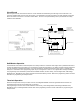
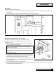
Placement
Refer to Figure 9 for system placement.
• Set the media tank on a solid, level surface near water, drain and electrical facilities. Place the outlet (black coupling) of the
tank on the left.
• Set the brine system on a at, smooth, solid surface as near the media tank as possible.
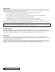
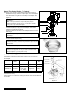
Mount The Control Valve - 3/4” Control
See gure 10 for a visual on mounting the control valve to the tank.
As shipped from the factory the Culligan Medallist Series
®
3/4” control is
equipped as a 8” unit.
1. Remove the two plastic caps from the tank couplings and lubricate the
coupling O-rings with silicone lubricant.
2. The control valve is marked also with “IN” and “OUT”. Place the control
onto the tank with the inlet and outlet of the control corresponding with the
inlet and outlet of the tank. Press rmly onto the couplings.
3. Remove the two u-clamps and screws from the parts pack. Install the
clamps on both sides of the control as indicated in Figure 10 and secure
them with the screws.
4. Peel off the protective lm off the circuit board label.
5. Attach the appropriate Culligan Medallist Series data plate that’s included in the small parts pack onto the back of the control
(over the holes used for the solenoid valve).
Figure 9
Figure 10
Note: Do not use a petroleum base lubricant, for this will cause
swelling of the rubber parts.
Note: The black molded tank adapter is marked with “IN” and “OUT”,
corresponding to the inlet and outlet of the tank. Position the tank with
the inlet coupling on the right and the outlet coupling on the left as you
face the front of the tank.